Acousto-Optic Q‑Switch Pulse Instability? 3 Hidden Causes of Laser Pulse Drop Outs
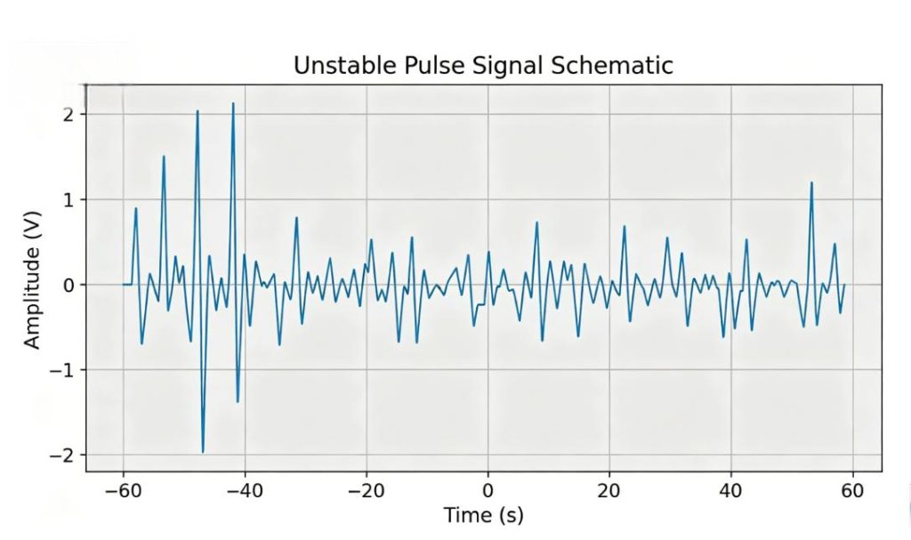
After you set up the laser, it ran for several hours without any problems. Then you noticed that the pulse energy was fluctuating wildly, and sometimes the pulses even disappeared, and the light spot began to flicker.
In this situation, most engineers would first replace the Q-switch. But this is expensive, and usually it doesn’t solve the problem.
I have seen this situation in industrial laser cutting systems, laser radar prototypes, and research laboratories. In most cases, the Q-switch itself is not the problem; the real problem lies elsewhere in the system.
This article will introduce three hidden reasons for the unstable pulses. The inspection time for each reason does not need to be very long. And except for a basic oscilloscope and thermometer, no special tools are required. Let’s get started.
Cause 1: RF Driver Frequency Mismatch with Your Laser Cavity Length
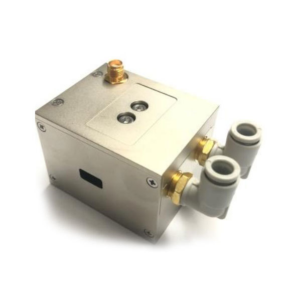
Your optical-Q-switching device requires a radio frequency driver. This driver outputs a specific frequency. If this frequency does not match the length of the laser cavity, unstable pulses will be generated.
How Cavity Resonance Affects the Performance of Q-Switching
When radio frequency power is applied, the Q-switch generates a grating inside the crystal. This grating causes the light to diffract out of the cavity. When the radio frequency power decreases, the loss of the cavity suddenly drops, thereby forming a pulse.
Only when the radio frequency matches the round-trip time of the cavity can this mechanism operate stably. However, even if the frequency deviation is only 0.1%, the grating cannot align with the nodes of the cavity. As a result, the Q-switch is incomplete and there are fluctuations between pulses.
How to Calculate the Correct Frequency for Your Cavity?
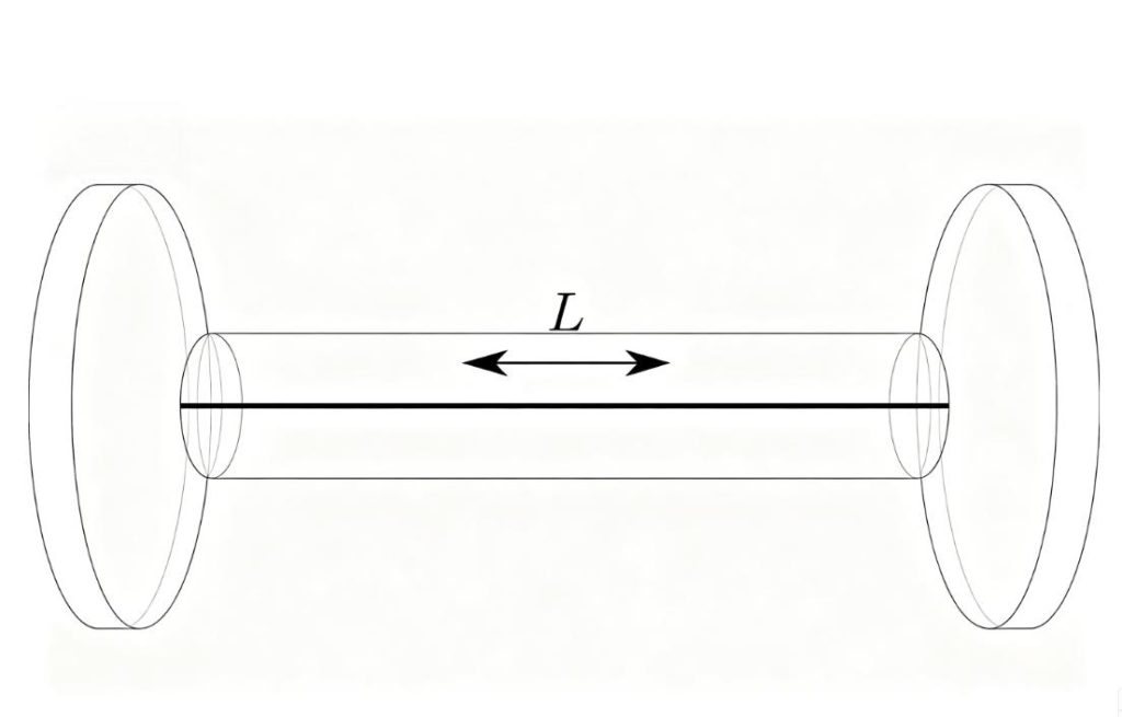
Here’s the formula:
f = c / (2 × L)
Where:
f = required RF frequency (Hz)
c = speed of light (3 × 10⁸ m/s)
L = optical cavity length (meters)
Example: a 1.2-meter cavity needs 125 MHz. A 0.8-meter cavity needs 187.5 MHz.
Compare this number to your driver’s rated frequency. If they don’t match within ±0.05%, that’s your problem.
Why Your Driver Might Drift Off Frequency Over Time?
Even if the initial frequency you used is correct, the driving unit will still drift. Aging components, poor temperature control within the driving unit, or aging of the oscillator circuit can all cause the output frequency to deviate by 0.1% to 0.3%.
I have seen some driver units whose initial frequency was 124.2 MHz. However, after being used daily for two years, it drifted to 124.8 MHz. This 0.5% drift was sufficient to cause the loss of random pulses.
How to check? Use a frequency meter or an oscilloscope with an FFT function to measure the actual output frequency of the driver unit. Don’t trust the labels on the packaging box.
Cause 2: Temperature Changes Inside the Crystal
Acousto-optic crystals have temperature dependence. It is possible for a temperature difference of 5 degrees Celsius to greatly affect their performance.
Effect of Temperature on Diffraction Efficiency
In terms of temperature variation, the crystal used for the Q-switch undergoes expansion and contraction. These include:
- Sound velocity inside the crystal
- The Bragg angle matching condition
- Refractive index
A change in temperature during operation results in variations in these parameters. This leads to decreased diffraction efficiency. Your laser sees higher cavity loss at some times and lower loss at others. That gives you unstable pulse energy.
What Should You Be Looking For With Regards to Temperature?
Operate the laser for an hour. Every 10 minutes, check the Q-switch housing (be careful, since it could be hot). Observe whether there is consistency in the temperature or whether it rises continuously.
Then proceed with the following experiment:
- Allow the laser to cool off completely (through the night).
- Operate the laser and take note of its pulse energy for 30 seconds.
- Wait 30 minutes, then record again
- Compare the two recordings
If there are fluctuations in pulse energy after the 30-minute run, then temperature could be the issue.
Cooling Checks You Can Do in 5 Minutes
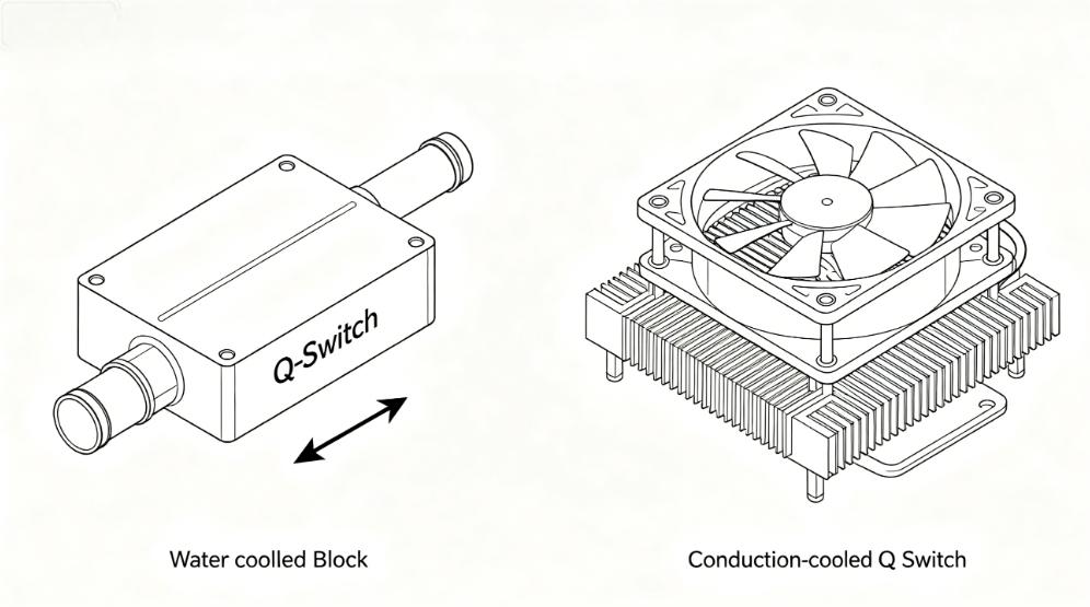
Water-cooled and conduction-cooled Q-switch cooling check points
Water-Cooled Q-Switch:
- Verify the water flow rate according to the manufacturer’s specifications
- Touch the water lines at the inlet and exit ports to see if there is a temperature difference
- Look for bubbles in the water line (bubbles kill cooling efficiency)
Conduction-Cooled Units:
- Does the thermal paste need to be renewed? The paste degrades with time.
- Is the correct amount of torque applied to the unit’s mountings? If too little, no proper heat dissipation. If too much, crystal damage may occur.
- Is the heatsink fan working? Listen for unusual noise or slow speed.
Cause 3: Noise from Your Modulation Source
Your Q-switch driver receives a TTL or analog control signal from something – a laser controller, a signal generator, or an OEM circuit. If that signal generator has noise, you will have unstable pulses.
Reasons Why a Jittery Trigger Signal Leads to Unstable Pulses
The driver relies on the clean rising edge to start and stop the RF output. In case the trigger has jitter, overshoots, or a non-square shape, the driver fires slightly differently each time.
At 50 kHz pulse repetition frequency, any 10 ns difference causes energy variations. At 100 kHz, things get even worse.
Ground Loops and Poor Shielding
Ground loops occur when your control unit and driver are connected to two different power sources. The electrical currents flowing through the shield of the signal cable cause noise in the trigger signal.
- Solution: Connect both units to the same power strip. Utilize differential signals if they are available.
- Poor shielding: Utilize coaxial cable for your trigger signal. Avoid running the signal cable parallel to AC power cables and motor drives. If crossing an AC power cable is inevitable, do so at a right angle.
Checking Your Trigger Signal Using An Oscilloscope
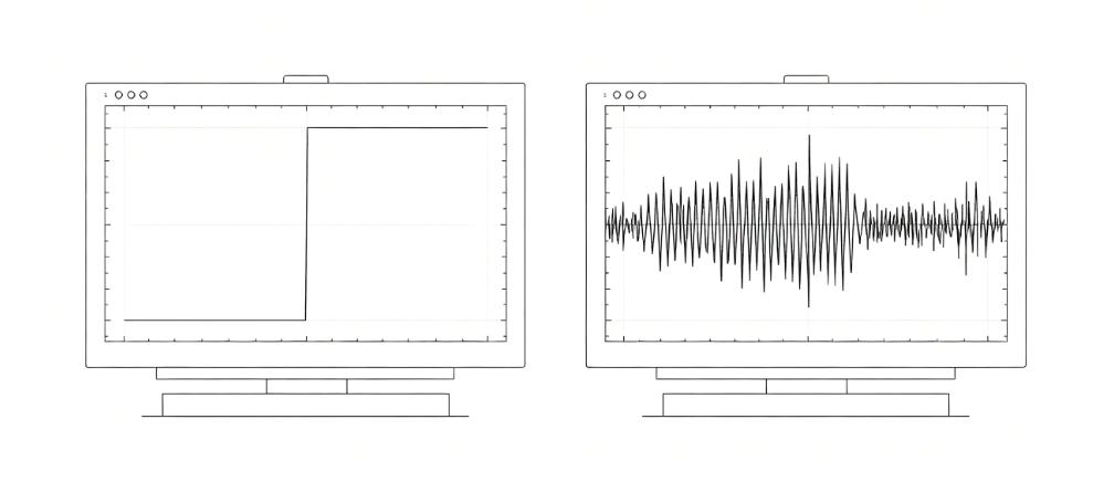
Use the oscilloscope probe to connect the signal on the trigger input side of the driver (not the controller side). Observe the following:
- Clear rise edge: Below 100 ns rise time and no overshoot past 5.5V
- Period stability: No jitter on the fall edge
- No Spikes: No extra pulses between your intended triggers
If you see ringing (oscillations after the edge), add a 100-ohm resistor in series near the driver input. If you see slow edges, check your cable length – more than 3 meters needs a line driver.
Your 20-Minute Troubleshooting Checklist
Before ordering a replacement, run through these seven checks. No special tools required – just an oscilloscope and a few minutes.
| Step | Check | Time |
| 1 | Look at the trigger signal on the oscilloscope | 5 min |
| 2 | Inspect the coax cable for damage | 2 min |
| 3 | Compare the measured frequency to the cavity length formula | 1 min |
| 4 | Check water flow or heatsink contact | 3 min |
| 5 | Feel the Q-switch housing temperature after 30 min run | 5 min |
| 6 | Check for ground loops (same power strip) | 2 min |
| 7 | Inspect coax cable for damage | 2 min |
That’s roughly 20 minutes of work, depending on how fast you move through the checks.
If you’ve done all seven and the problem is still there, your Q-switch itself may have failed. Not every Q-switch can handle real-world thermal cycles or RF stress over time.
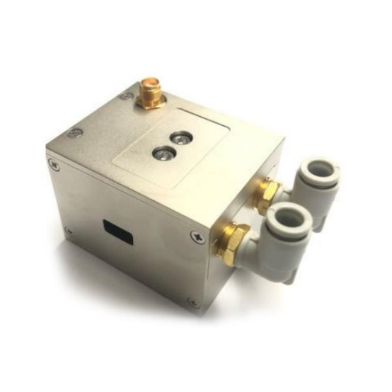
When you need a replacement that actually holds its calibration, take a look at our acousto-optic Q-switch series – built with proper heat dissipation and tested for long-term stability. Or just email us your setup. We’ll tell you if our unit fits your cavity before you buy anything.