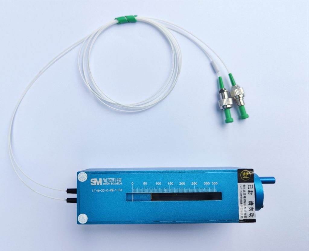
Electric Optical Fiber Delay Line
The third-generation electric fiber delay line (optical fiber delay line) offers exceptional performance for a wide range of applications. Its unique design delivers high precision and low insertion loss, ensuring continuous and reliable operation. The delay range spans picoseconds to femtoseconds, making it versatile for various needs. Additionally, it boasts high reliability, low polarization-related loss (<0.1 dB), and low insertion change (<0.5 dB), all within a simple and compact structure. To meet specific requirements, customization options are available.
Characteristics of Electric Optical Fiber Delay Line
- Unique delay machinery, working continuously and reliably, wide delay range, customized delay accuracy to the user request, delay accuracy up to orders of magnitude ps & fs.
- High reliability, low polarization-associated loss (<0.1dB)
- Lower insertion loss change (<0.5dB)
- Simple and compact structure, good repeatability, excellent performance.
Applications of Electric Optical Fiber Delay Line
- Radar test, calibration
- Controlled antenna array
- Optical coherence tomography
- X radiography
- Fourier spectroscopic analysis
- Light interferometry
- Fibre optic sensor
- Optical time-domain effect measurement
- Optical buffer in a bit-calibrated optical network for time-division multiplexing (OTDM) of an optical network
- Differential Group Delay (OMD)
- Multiplexing at compensation time hours
- Fibre optic interferometer
Parameter of Electric Optical Fiber Delay Line
| Parameter | Metric |
| Wavelength coverage | C-band or L-band or other wavelengths |
| Light delay range | 0~100 ps continuous for 100ps model 0~330 ps continuous for 330ps model 0~660 ps continuous for 660ps model 0~1200 ps continuous for 1200ps model 0~1500 ps continuous for 1500ps model 0~3000 ps continuous for 3000ps model 0~4000 ps continuous for 4000ps model 0~5000 ps continuous for 5000ps model |
| Readout scale resolution | 10 fs for < 1000ps; 20fs for ≥ 1000ps |
| Repeat positioning accuracy | ±10fs for < 1000ps; ±20fs for ≥ 1000ps |
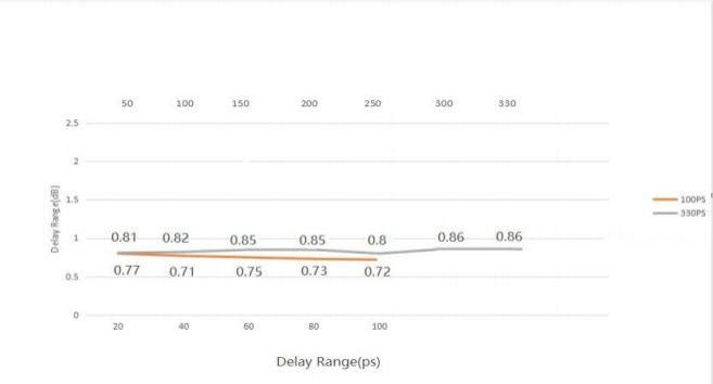
| Insertion loss | Min.0.6 dB, Max 0.8 dB for 100 ps Min.0.6 dB, Max 0.8 dB for 330 ps Min.0.8 dB, Max 1.0 dB for 660 ps Min.1.2 dB, Max 1.5 dB for 1200 ps Min.1.3 dB, Max 1.6 dB for 1500 ps Min.2.4 dB, Max 2.8 dB for 3000 ps Min.3.2 dB, Max 3.6 dB for 4000 ps Min.4.0 dB, Max 5.0 dB for 5000 ps The above reference values for insertion loss are only applicable to the C-band or L-band. The fiber type is SMF-28e. If other wavelengths or fiber types need to be selected, the loss shall be subject to the final evaluation. |
| Return loss | > 55 dB |
| Extinction ratio | > 18 dB (PM) |
| Light withstand power | Max 500 mW |
| Working temperature | -10°C ~ 80°C or -40°C ~ 80°C (GJB) |
| Frequency of oscillation | GJB 150A |
| Storage temperature | -50 ~ 85°C |
| Fiber type | Corning SMF-28, or Fujikura PM Panda fiber |
| Dimensions (L x W x H) | 150 * 38 * 38 (100 ps) 150 * 38 * 38 (330 ps) 200 * 38 * 38 (660 ps) 215 * 48 * 38 (1200 ps) 290 * 48 * 38 (1500 ps) 328 * 48 * 38 (3000 ps) 392 * 48 * 40 (4000 ps) 485 * 48 * 40 (5000 ps) |
Loss; Performance Value:
Performance value:
Product ordering information:
| SM-E | Delay | Wavelength | Fiber type | Fiber length | Junctor |
| 10=100ps 33=330ps 66=660ps 120=1200ps 150=1500ps 300=3000ps 400=4000ps 500=5000ps XX=others | C=C-band L=L-band 532=532nm 633=633nm 780=780nm 840=840nm 850=850nm 980=980nm 103=1030nm 106=1060nm 131=1310nm 148=1480nm 165=1650nm | S9=SMF 900um M5=MME 50/125/900 M6=MMF 62.5/125/900 PM=PM Panda XX=others | 1=1.0m 2=2.0m X=others | NE=None FA=FC/APC FC=FC/PC SA=SC/APC SC=SC/PC ST=ST/PC LA=LC/APC LC=LC/PC XX=others |
Instructions For Optical Fiber Delay Line
Wiring method:
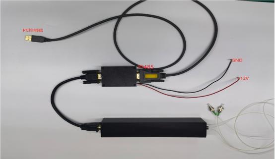
1)Our company provides electric delay lines and their accessories, including:
- Delay Line Body
- drive controller
- USB to RS485 adapter cable
- Serial port cable
Power supply mode: DC 12V, 1-1.5A, red line for positive pole, black line for negative pole.
2)The DB9 serial port on the same side of the power supply line is a USB to RS485 adapter cable connected to the computer control end, with the USB end connected to the computer and the other side connected to a fiber optic delay line. As shown in the picture:
Debugging Debugging
- Debugging method for upper computer:
After connecting the device as shown in Figure 1, turn on the delay line control as shown in Figure 2, select the corresponding specification, choose the corresponding serial port, click connect, and the delay line will perform initialization zeroing action. The zeroing time depends on the current position.(Do not operate during the zeroing period. Normal operation can only be carried out when the delayed position is displayed as “0”)
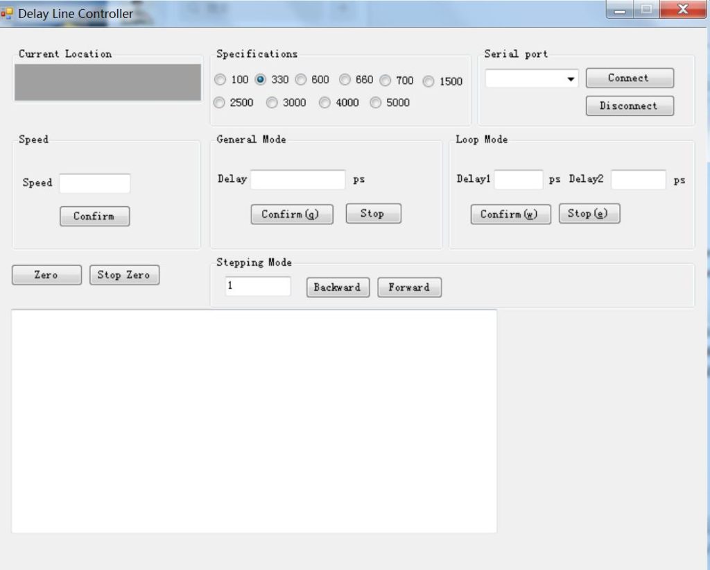
Explain:
- Specification selection: Please make sure to select the corresponding delay line range for use.
- Speed setting: The speed setting value range is (-5000 to -190000). Note that the value is negative, and it is recommended to use the default speed without modification unless necessary.
- General mode: Enter the corresponding delay value, confirm the motor, and start running. If you need to stop halfway, click Stop.
- Loop mode: It can control the delay line to move back and forth between the corresponding two delays.
2. Debugging method for upper computer:
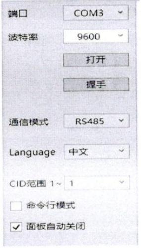
The serial port settings are shown in Figure 3 (the port is selected according to the actual situation)
ODL pin definitions: RS485
1-A, 2-B, other pins floating.