
How RF Driver Impedance Mismatching Damages Your Acousto-Optic Modulator?
In high-performance laser systems, the crucial functions of acousto-optic modulators (AOM) and Q switches are to control pulse characteristics and beam quality. However, engineers may frequently encounter problems such as sudden performance degradation, thermal drift, or crystal fracture.
Although these faults are usually attributed to optical power density or manufacturing defects, the real cause often lies in the electrical interface: RF impedance mismatch. This article will deeply analyze the physical principles of RF impedance mismatch, explain how it damages optical components, and discuss how we can prevent RF impedance mismatch.
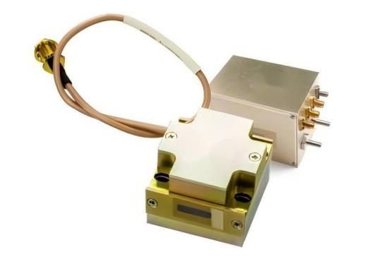
What is RF Impedance Matching in Acousto-Optic Systems?
To understand impedance matching, one must first understand how acoustic-optic devices convert energy.
The acoustic-optic Q switch relies on a piezoelectric transducer (typically lithium niobate, LiNbO3), which is bonded to an acoustic medium (such as fused quartz or tellurium dioxide (TeO2)). The RF driver provides high-frequency electrical signals to the transducer, which converts electrical energy into sound waves. The sound waves propagate through the crystal, forming the grating required for the diffraction laser beam.
The impedances of the RF source, coaxial cable, and the acoustic-optic modulator transducer are kept the same to achieve efficient power transmission. In the laser industry, the common standard is 50 ohms. When the impedances of all components are perfectly matched to 50 ohms, 100% of the forward RF power will be absorbed by the transducer and converted into acoustic energy.
When the load impedance deviates from 50 ohms, impedance mismatch occurs. When the radio frequency wave encounters this mismatch, it cannot be fully absorbed. At this time, some of the radio waves will be reflected back to the driver and form a standing wave in the cable.
Engineers use two key parameters to quantify this matching efficiency:
- Voltage Standing Wave Ratio (VSWR): A perfect match results in a VSWR of 1.0:1. A higher ratio indicates severe mismatch.
- Return loss (dB): This indicates the ratio of reflected power to incident power. A high return loss (for example, greater than 20 dB) implies very little reflection, while a low return loss (for example, less than 10 dB) suggests that a significant amount of reflected energy enters the system.
How Mismatching Damages Your AOM
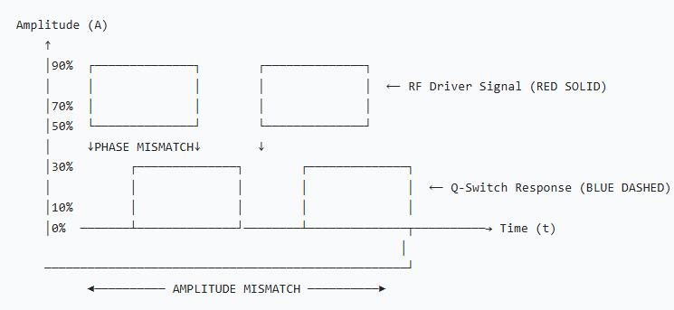
When an impedance mismatch occurs, the unabsorbed electrical energy does not simply disappear. It manifests as a sequence of thermal and mechanical stresses that degrade and eventually destroy the acousto-optic component through three primary mechanisms:
A. Reflected Power and Severe Thermal Lensing
The immediate consequence of a low return loss is that the rejected RF energy is converted into heat concentrated precisely at the transducer interface. This localized thermal spike creates a severe temperature gradient across the crystal matrix. Because the refractive index of optical materials changes with temperature (the dn/dT effect), this gradient induces thermal lensing.
Thermal lensing distorts the wavefront of the passing laser beam, turning a pristine Gaussian profile into an aberrated, unstable shape. Furthermore, it degrades beam pointing stability, causing the focal spot of the laser to drift during operation—a catastrophic outcome for high-precision micro-machining or marking systems.
B. Piezoelectric Transducer Degradation and Delamination
The prolonged thermal and electrical stress caused by standing waves takes a heavy toll on the atomic structure of the transducer. High VSWR generates voltage peaks that can exceed the dielectric breakdown threshold of the piezoelectric material. Simultaneously, excessive heat weakens the specialized metal bonding layers that adhere the transducer to the optical crystal. Over time, this leads to micro-fractures or complete delamination of the transducer. As the physical contact degrades, the device’s diffraction efficiency drops permanently, forcing the operator to increase RF power, which accelerates the failure loop.
C. Reverse Amplifier Destruction in the RF Driver
The damage path is bidirectional. The reflected RF wave travels backwards into the output stage of the RF driver. The power amplifier (PA) transistors inside the driver are engineered to push energy outward into a 50 Ω load. When forced to absorb their own reflected energy, these transistors undergo severe overheating, leading to thermal runaway and immediate electrical failure of the driver circuitry.
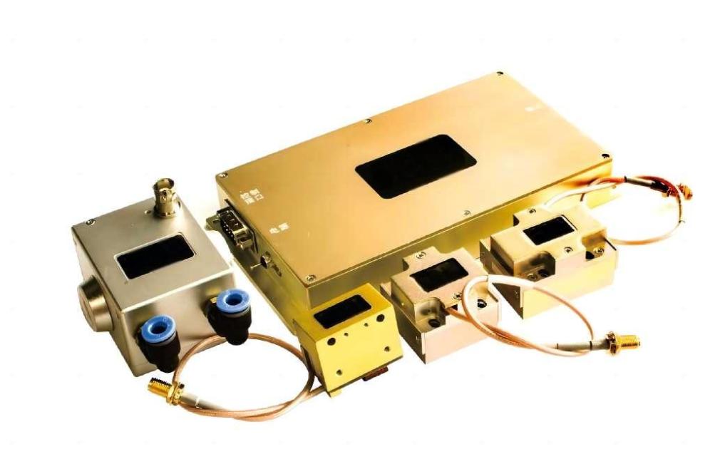
Common Causes of Impedance Mismatching
Impedance mismatch is not usually caused by a single component defect, but is introduced during system integration or routine maintenance. The most common reasons include the following points:
- Poor interconnection cables: Using general-purpose non-50 Ω coaxial cables, or selecting cables of inappropriate length (which can act as an impedance transformer at high frequencies), may cause the nominal matching to deviate significantly from the specifications.
- Connector wear and contamination: Loose, overly tightened, or contaminated (with dust or oil) SMA, BNC or SMB connectors will introduce severe capacitive or inductive parasitic impedance at the connection points.
- Frequency mismatch: Using incompatible RF frequencies to drive acoustic-optic devices. For instance, attempting to use an 80 MHz driver and a Q switch with a center frequency of 41 MHz will prevent the transducer from resonating, thereby causing severe reflections.
How to Prevent Damage and Optimize Performance
Mitigating the risks of impedance mismatching requires a disciplined engineering approach to system setup and component selection:
- Deploy Matched Component Ecosystems: The safest architecture is to deploy RF drivers engineered natively alongside the specific acousto-optic modulator. Factory-calibrated pairs ensure that impedance matching is optimized across the full operational bandwidth.
- Enforce Strict Interconnect Protocols: Always utilize high-grade, double-shielded 50 Ω coaxial cables cut to precise manufacturer-recommended lengths. Inspect connectors with an optical loupe and tighten them using calibrated torque wrenches to eliminate structural signal reflection.
- Utilize Active RF Drivers with Built-in Protection: Advanced RF drivers incorporate vital protective circuitry, such as automatic first-pulse suppression and high-VSWR shutdown thresholds. If an impedance anomaly occurs, the driver instantly truncates the RF output before catastrophic thermal accumulation takes place.
Final
Achieving stable, long-term performance from your laser system requires careful attention to the electrical interface. RF impedance mismatching is a silent threat that degrades beam quality, ruins diffraction efficiency, and permanently damages expensive acousto-optic modulators and drivers. By strictly adhering to 50 Ω transmission standards, utilizing precision connectors, and choosing protective, factory-matched RF drivers, you can completely isolate and eliminate this failure mechanism.
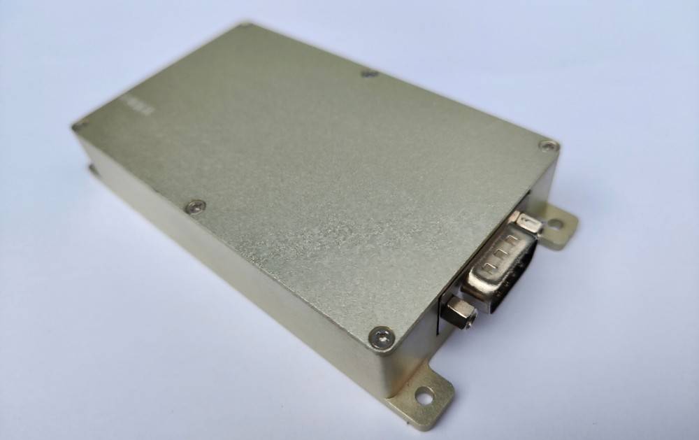
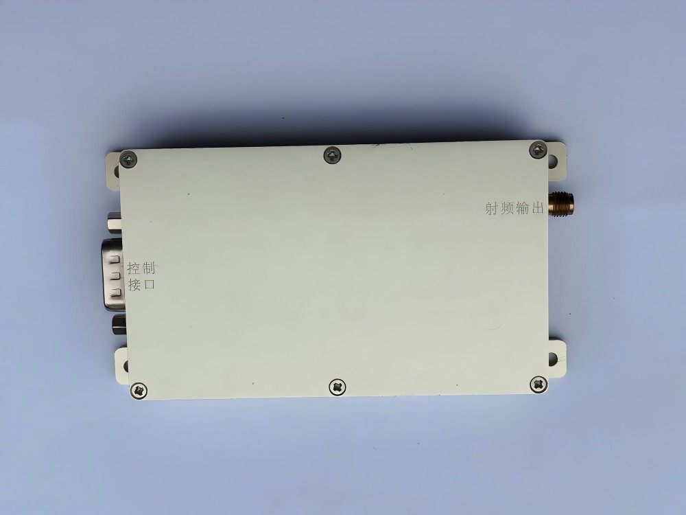
Maximize System Lifespan with Matched RF Architecture: At SMART SCI&TECH, we manufacture proprietary, ultra-compact acousto-optic Q-switches and modulators optimized alongside our high-stability V-type and W-type RF Drivers. Supporting advanced digital/analog modulation and robust first-pulse suppression under 40W and 70W power thresholds, our systems guarantee optimal VSWR matching. Contact our Chongqing-based engineering team today for custom impedance-matched solutions.