
How to Build a Fiber-Based True Time Delay System?
The fiber-based true delay system can provide precise optical delay in radio frequency (RF), microwave photonics, optical fiber sensing, and laser systems. Its typical architecture is:
Laser → Modulator → Optical Delay → Detector → RF/Optical Processing
The system design is not simply adding an extra section of fiber; it also needs to comprehensively consider indicators such as delay quantity, optical loss, bandwidth, dispersion, and stability. Here is an introduction to a practical system design method.
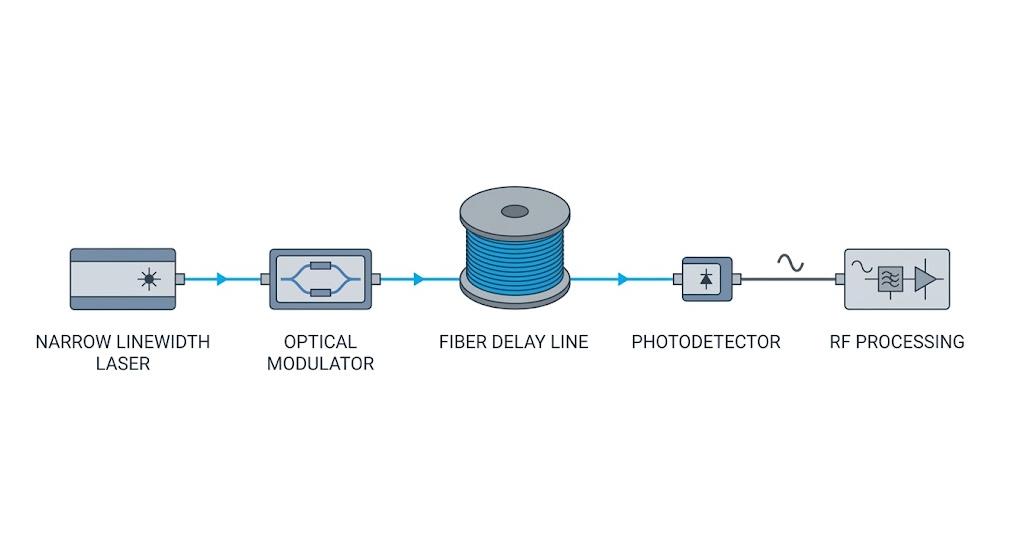
How Much Fiber Do You Actually Need?
If a fixed and definite delay is required, using a fiber delay line with clearly specified specifications is usually easier for system integration than manually building a long optical fiber link.
The first question is usually quite simple: How Much is the delay required?
For an optical delay line, the propagation delay can be estimated using the following formula:
Delay time (τ) = Optical fiber length (L) × Group refractive index (n_g) ÷ Speed of light (c)
That is:
τ = n_g × L / c
Where:
- τ = Delay time
- n_g = Refractive index of the optical fiber group
- L = Length of the optical fiber
- c = Speed of light
For example, if the group refractive index is approximately 1.47, to achieve a delay of 1 μs, approximately 204 meters of optical fiber is required.
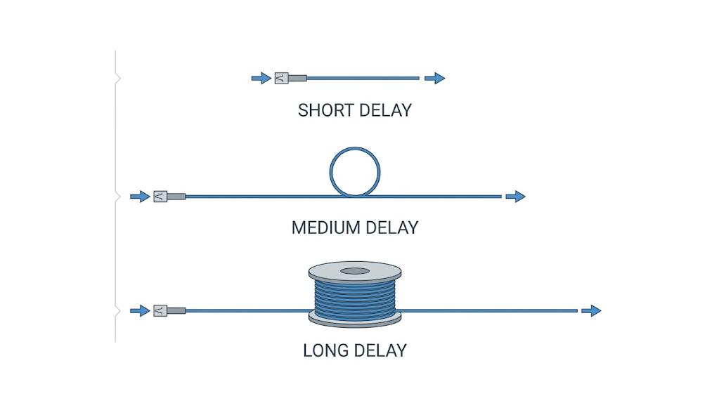
This calculation only provides a reference starting point; in actual system design, factors such as fiber length tolerance, connector effects, temperature changes, and the group refractive index of the fiber at the working wavelength need to be considered as well.
What Determines the Quality of the Delayed Signal?
Precise delay is just the foundation. The delayed signal still needs to maintain sufficient quality to meet the requirements of the subsequent system.
Three parameters need to be focused on:
- Insertion loss determines the remaining optical power of the signal after passing through the delay path. As the length of the optical fiber increases or the number of components in the optical path increases, the importance of the power budget will also increase.
- For broadband or high-speed signals, dispersion is particularly important. The propagation delay of different frequency components is different, which may affect signal integrity.
- For phase-sensitive applications such as coherent detection and interferometric measurement, polarization characteristics also need to be considered. Polarization changes in the optical fiber path may reduce measurement stability.
Therefore, when choosing an optical delay line, in addition to the delay time, parameters such as wavelength, loss, bandwidth, dispersion and polarization should also be comprehensively considered.
Where Do AOM and Laser Performance Enter the Equation?
The optical fiber is only a part of the signal transmission path. The performance of the light source and the modulator also affects the quality of the delayed signal.
For applications that require high coherence and frequency stability, narrow-linewidth lasers can provide a more stable optical carrier, suitable for coherent detection, interferometric measurement, and precise photonic measurement.
If rapid optical modulation or frequency shift is needed, an acousto-optic modulator (AOM) can be added. The typical configuration is as follows:
Narrow linewidth laser → AOM → Optical Delay Line → Detector
The specific configuration depends on the system requirements, including amplitude modulation, frequency shift, pulse control, and other optical signal processing requirements.
Therefore, the delay section cannot be designed independently and needs to be matched with the light source and modulator in terms of wavelength, optical power, modulation method, and other parameters.
Fixed Delay or Adjustable Delay: Which Architecture Fits Your System?
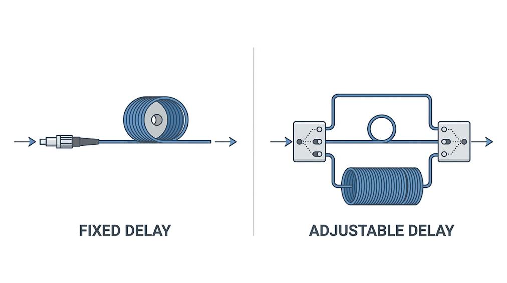
The flexibility of delay is also an important consideration in system design.
If the system only requires fixed and known delays, such as 100 ns, 1 μs, or 10 μs, optical delay lines are usually a simple and reliable choice. Their delay is mainly determined by the length of the optical fiber path, and the architecture is relatively intuitive. If the system needs multiple or dynamically changing delay values, a tunable architecture is more suitable.
| Requirement | Suitable Approach |
| Fixed delay | Fiber Delay Line |
| Long optical delay | Fiber Delay Line |
| Multiple delay values | Electric ODL |
| Programmable delay | Electric ODL |
| Dynamic switching | Programmable delay architecture |
For example, in scenarios where flexibility is more important than fixed delays, one can consider electrically controlled optical delay lines (Electric ODL) or programmable optical delay solutions.
The final choice depends on whether the system needs to adjust the delay during operation.
How Do You Make the Whole System Work as One?
After the architecture is determined, it is necessary to further match each component to build a complete optical and radio frequency link.
At least the following parameters should be verified:
- Wavelength – Ensure that all optical components support the working wavelength.
- Required delay – Determine the length of the optical fiber or the range of delay.
- Optical power – Ensure that the modulator, optical fiber, and detector are within the allowable range.
- Modulation bandwidth – Meet the signal bandwidth requirements.
- Radio frequency frequency and power – When using an acousto-optic modulator (AOM), it is necessary to focus on matching these parameters.
- Detector bandwidth – Meet the requirements for the recovered radio frequency or high-speed signal.
- Insertion loss – Control it within the available power budget.
If the system uses an AOM, its radio frequency driver also needs to be matched in terms of working frequency, radio frequency power, modulation bandwidth, and impedance with the AOM.
The optical true delay system is not a simple combination of multiple independent components. The laser, modulator, delay line, detector, and radio frequency/optical signal processing unit need to match each other on key parameters to form a stable complete link.
For applications with specific delay, wavelength, bandwidth, or packaging requirements, customized component configuration is usually more suitable than directly using standard components. SMART SCI&TECH provides optical delay lines, acousto-optic modulators, AOM drivers, narrow linewidth lasers, and optical delay solutions for research, industrial, and OEM applications. If there are specific delay requirements or system configuration requirements, you can contact the engineering team for further discussion.