
How to Choose Optical Delay Range for an Interferometer?
To select the appropriate optical delay range, three issues need to be considered first: What is the required optical path difference (OPD) to cover? What kind of delay resolution is needed? How fast does the system scanning speed need to be?
The goal is to cover the entire measurement range without sacrificing accuracy, signal quality, or system stability.
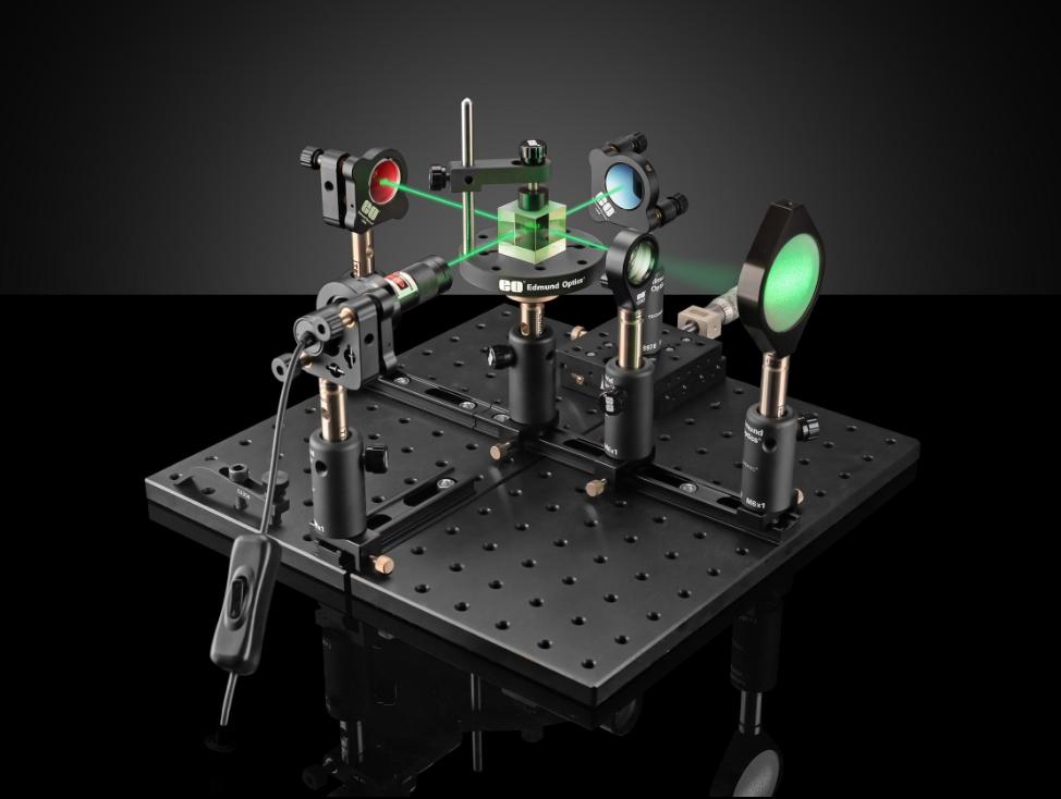
Key Factors for Choosing Optical Delay Range
1. Required Optical Path Difference (OPD)
First, determine the maximum optical path difference that your interferometer needs to compensate for or scan. This should take into account the initial mismatch between the reference arm and the measurement arm, the expected optical path changes, and the required scanning range.
The available delay range must cover the entire working range and leave a reasonable margin to accommodate alignment requirements and system tolerances. Do not choose components based solely on the nominal maximum range.
2. Delay Resolution and Precision
Resolution, precision, and repeatability are different technical indicators. Resolution refers to the smallest delay increment that can be controlled or measured; precision describes the degree to which the actual delay matches the target value; repeatability reflects the consistency of repeated adjustments.
For precise interferometric measurements, all these indicators are important. A wide delay range does not necessarily mean high precision; therefore, these indicators should be evaluated based on your measurement requirements.
3. Scanning Speed and Dynamic Performance
For applications involving continuous scanning or time-sensitive measurements, consider the maximum scanning speed, acceleration, stabilization time, and control response characteristics.
Even if the travel of the optical delay line is sufficient, it may not meet the requirements of the measurement cycle time. The dynamic performance should be evaluated under the expected working conditions, rather than relying solely on the maximum speed indicator.
4. Optical Performance and Light Source Compatibility
Insertion loss, polarization behavior, dispersion, and operating wavelength can affect interference visibility and signal quality. Depending on your system requirements, suitable passive optical components can help address optical routing and isolation needs, while narrow linewidth lasers may be relevant for precision measurement applications.
For systems requiring active laser control, fiber-optic acousto-optic modulators and compatible acousto-optic modulator drivers may also be relevant, depending on the optical architecture.
How to Calculate the Required Optical Delay Range
The required range should be calculated based on the optical path difference (OPD) that the system needs to cover.
For light propagating in a vacuum, the relationship between the optical path difference (OPD) and the time delay is:
Δτ = OPD / c
Among them:
- Δτ represents the time delay difference.
- OPD stands for optical path difference.
- c is the speed of light in a vacuum, approximately 3 × 10⁸ m/s.
For example, an OPD of 1 mm corresponds to approximately 3.33 ps of time delay; thus, an OPD of 12 mm corresponds to approximately 40 ps.
For a typical double-pass delay line using a moving mirror, the change in optical path difference is approximately twice the mechanical displacement of the mirror:
OPD ≈ 2 × Mechanical travel
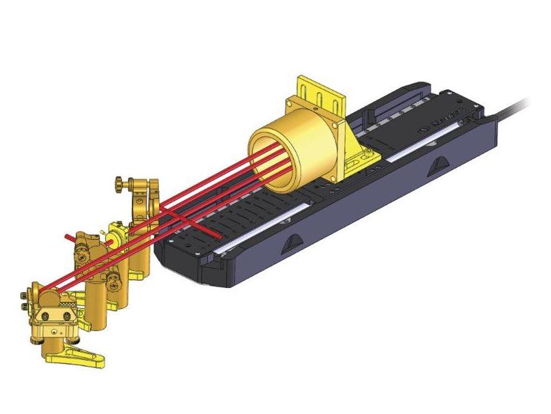
If the required OPD adjustment range is 12 mm, the mirror needs approximately 6 mm of mechanical travel. The corresponding time delay change is approximately 40 ps.
The above calculations are based on the conventional double-pass configuration. Other optical architectures may require different conversion methods. Be sure to confirm the manufacturer’s specification parameters refer to mechanical travel, single-pass delay, round-trip delay or optical path difference.
Finally, it is necessary to distinguish between the total available range and the actual available scanning window. If the system needs to scan near a specific working point, ensure there is sufficient travel in the required direction and reserve alignment and positioning tolerances.
Optical Delay Range for Different Applications
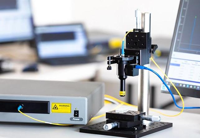
The appropriate delay range depends on the measurement objective and optical configuration. The following table summarizes the main selection priorities.
| Application | What to Prioritize |
| Precision interferometry | OPD coverage, positioning accuracy, and stability |
| Fiber-optic sensing | Required path difference, insertion loss, and polarization stability |
| Optical coherence tomography (OCT) | Imaging depth, scan range, and scanning speed |
| Quantum optics | Relative delay, timing precision, and phase stability |
| Optical testing | Required delay span, calibration accuracy, and repeatability |
For precise interferometric measurement, stable and repeatable delay control may be more important than maximizing the adjustment range. Fiber optic sensing systems also need to fully consider the impact of optical loss and environmental factors.
In optical coherence tomography (OCT), the required scanning range depends on the expected imaging depth and system architecture; in the field of quantum optics, relative timing and synchronization are often the primary considerations.
The above are only general selection guidelines, not hard technical indicators. Even when applied to the same scenario, two systems may still require different delay ranges due to differences in wavelength, optical path layout, measurement methods, and operating conditions.
Final: Choose the Right Optical Delay Range
Choosing the right optical delay range starts with calculating the required OPD, followed by evaluating delay resolution, accuracy, scanning speed, and optical performance. The goal is to match the specifications to your measurement requirements while maintaining system stability and efficiency.
Beyond delay range, the performance of an interferometer also depends on the compatibility of its optical components and supporting electronics. Lasers, acousto-optic devices and their drivers, as well as active and passive optical components, can play important roles in laser-based measurement, fiber-optic sensing, and advanced research systems.
As a high-tech company specializing in the R&D, manufacturing, and sales of these products, we provide optical and photonic component solutions for applications ranging from laser manufacturing to fiber-optic sensing and quantum research.
Need Optical Components for Your Application?
Contact SMART SCI&TECH to discuss your operating wavelength, optical configuration, and system requirements. We can help you explore suitable lasers, acousto-optic devices, driver electronics, and other optical components for your application.