
How to Measure AOM Diffraction Efficiency?
The diffraction efficiency of an AOM (acousto-optic modulator) is usually evaluated by the ratio of the power of the first-order diffraction light to the incident light power. However, in practical applications, the measurement results are affected by factors such as RF (radio frequency) driving conditions, alignment of the optical path, polarization state, beam size, and the collection method of the first-order diffraction light.
Therefore, meaningful efficiency measurement is not just about obtaining a numerical value; it is more important to determine the actual working state of the AOM under specific conditions.
Measure the Incident and First-Order Optical Power
The basic calculation formula is:
Diffractive efficiency (%) = P₁ / Pᵢₙ × 100%
Where, Pᵢₙis the optical power entering the AOM, and P₁ is the power of the first-order diffracted beam.
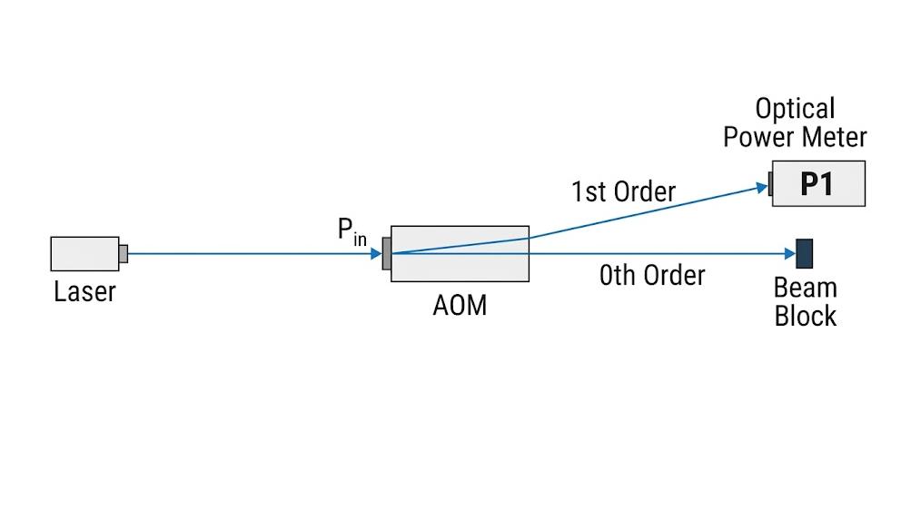
For example, if the input optical power is 100 mW and the power of the first-order diffracted beam is 80 mW, the diffraction efficiency is 80%.
The measurement device should separate the first-order diffracted light from the zero-order light and the scattered light:
Laser → AOM → First-order beam → Power meter
The power meter should fully receive the first-order beam to avoid beam obstruction or truncation. At the same time, zero-order light should be blocked or spatially separated to avoid its influence on the measurement results.
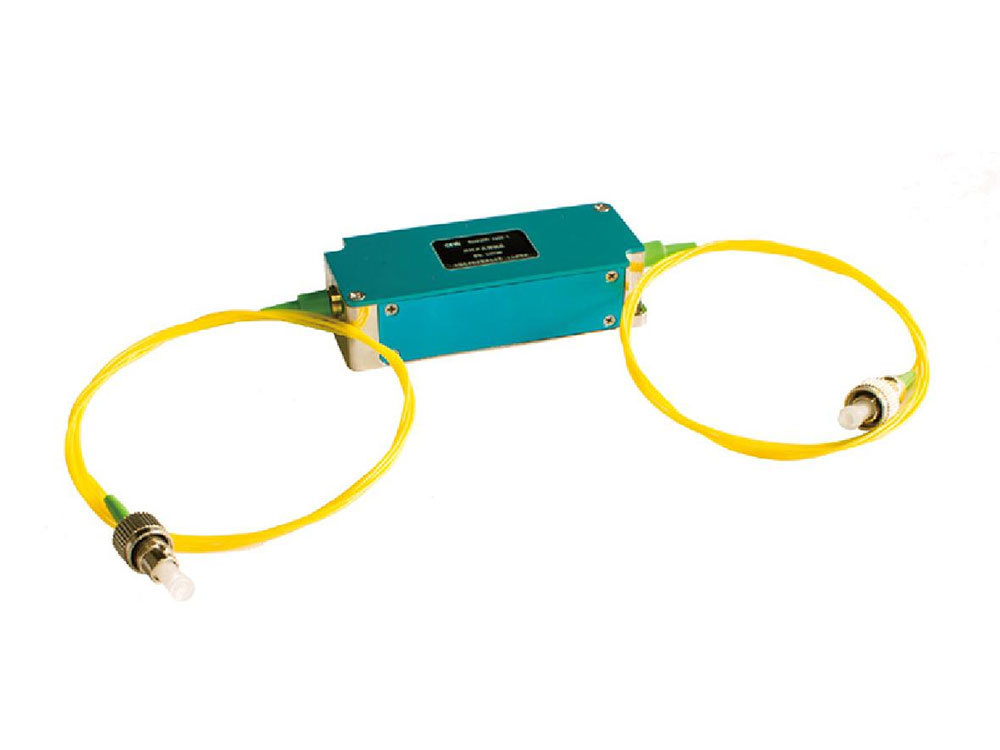
For free-space AOM, beam collimation and receiving geometric layout are particularly important. For fiber-coupled AOM, the coupling condition is mainly determined by the device, but the input optical power and measurement position still need to be clearly defined.
Optimize the AOM for Maximum Diffraction Efficiency
The initially measured power should not be directly regarded as the maximum efficiency of the AOM.
Before recording the final results, the key conditions that affect the acoustic-optical interaction should be optimized, including:
- RF frequency
- RF driving power
- Optical alignment
- Bragg angle
- Polarization state
- Beam diameter
The RF frequency should be within the working range specified by the AOM. Deviation from the optimal working point may result in a decrease in the power of the first-order diffraction light.
For free-space AOM, optical alignment is also important. When adjusting the position and angle of the beam, the power of the first-order diffraction light should be monitored simultaneously, rather than completing all the alignment before applying the RF drive.
The polarization state also needs to comply with the technical specifications of the AOM. Depending on the device design and materials, there may be polarization dependence on the diffraction efficiency.
The goal of optimization is to establish stable and repeatable measurement conditions before comparing efficiencies or adjusting the RF power.
Measure Diffraction Efficiency Across RF Drive Power
A single RF power point does not show how the AOM behaves.
A more useful characterization is to gradually increase the RF drive power and record the first-order optical power at each point.
For example:
| RF Power | First-Order Power | Diffraction Efficiency |
| P₁ | — | — |
| P₂ | — | — |
| P₃ | — | — |
| P₄ | — | — |
| P₅ | — | — |
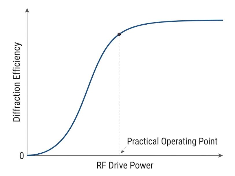
Calculate the diffraction efficiency at each point and plot the relationship curve between RF driving power and diffraction efficiency.
At lower RF driving powers, increasing the power usually leads to an increase in diffraction efficiency. As the acoustic-optical interaction intensifies, the efficiency gradually reaches saturation and no longer grows linearly.
Compared to a single efficiency value, the efficiency curve is more valuable for reference, as it can directly reflect the working state of the AOM as the RF power changes.
The highest RF power does not necessarily correspond to the optimal working conditions. Excessive RF power will increase the thermal load of the AOM and RF driver, and the efficiency improvement may be very limited. Therefore, the AOM test guide of CQ-SMART also suggests measuring the complete efficiency curve instead of simply believing that increasing the RF power can continuously improve the diffraction efficiency.
Identify the Factors Limiting Measured Efficiency
If the measured efficiency is lower than expected, the measurement conditions should be checked before replacing the AOM.
- Alignment of the optical path: For a free-space AOM, an improper Bragg angle or beam position will reduce the power of the first-order diffraction light. The beam should also pass through the effective aperture completely to avoid clipping.
- RF frequency: Confirm that the driving frequency complies with the working conditions of the AOM and is matched with the transducer and optical configuration of the device.
- RF driving power: If the RF power is too low, the AOM may not reach the expected efficiency. Conversely, continuing to increase the RF power beyond the effective working range may not necessarily improve the efficiency.
- Polarization and beam parameters: The polarization state, beam diameter, and divergence angle all affect the measurement results. Even if the RF conditions are correct, if the beam is too large, clipping occurs, or the alignment is poor, the efficiency may be low.
- First-order beam reception: The power meter should receive the entire first-order diffraction light. If part of the beam is clipped, the measured efficiency will be lower than the actual value.
Compare Measured Efficiency with the AOM Specification
Before confirming that the test conditions are consistent, one should not directly compare the measured efficiency with the nominal values in the data sheet.
At least the following parameters should be checked:
- Wavelength
- RF frequency
- RF driving power
- Beam diameter
- Polarization state
- Optical alignment
- Input optical power
- Measurement position
For example, the nominal diffraction efficiency of an AOM might be measured under specific wavelengths and RF powers. If the wavelength or RF power is changed during the test, the result may also change. The polarization state and beam characteristics can also affect the diffraction efficiency.
This is particularly important when comparing AOMs from different suppliers or of different models. Only when the test conditions are comparable, can the difference in nominal efficiency have practical reference value.
What to Record in an AOM Efficiency Test
Only when the testing conditions are clear, the measured diffraction efficiency has practical significance. When recording data, in addition to the efficiency values, key optical and RF parameters should also be retained, including the working wavelength, RF frequency and driving power, input optical power, and beam alignment status.
When repeating tests or comparing different AOMs, efforts should be made to keep the measurement conditions consistent so as to determine whether the efficiency change is due to the AOM itself or differences in optical and RF settings.
Therefore, an effective test record should include both the efficiency values and the corresponding testing conditions, rather than treating the efficiency percentage as an independent specification parameter.
Measuring AOM diffraction efficiency is not simply a matter of comparing input and first-order optical power. RF frequency and power, optical alignment, polarization, beam diameter, and measurement conditions can all affect the result. A repeatable test should therefore measure efficiency under clearly defined and consistent conditions.
If you are selecting or evaluating a fiber-coupled or free-space AOM, SMART SCI&TECH provides AOM solutions with different wavelength, frequency, and performance configurations for specific optical modulation requirements.