
Optimizing RF Power for Maximum Fiber AOM Diffraction Efficiency
The fiber acoustic-optic modulator (fiber AOM) is a core component in fiber lasers and sensing systems for achieving rapid intensity modulation, pulse selection, and frequency shift. In engineering applications, maximizing the first-order diffraction efficiency is the key to reducing signal loss.
However, excessively increasing the RF driving power does not linearly enhance the diffraction efficiency. The acoustic-optic interaction exhibits nonlinear characteristics. RF power beyond the saturation limit will be converted into waste heat, leading to thermal lensing effects, beam degradation, and polarization drift. Achieving the best performance requires balancing the Bragg diffraction saturation and long-term thermal stability.
Why Higher RF Power Fails to Boost AOM Efficiency
The Physics of Bragg Diffraction Saturation
The fiber AOM operates based on the acousto-optic effect. The RF driver inputs high-frequency electrical signals (typically 40–200 MHz) into the piezoelectric transducer, which converts them into acoustic waves in the acoustic-optical crystal (such as TeO₂ or fused quartz). The acoustic waves cause periodic changes in the refractive index, forming a dynamic grating.
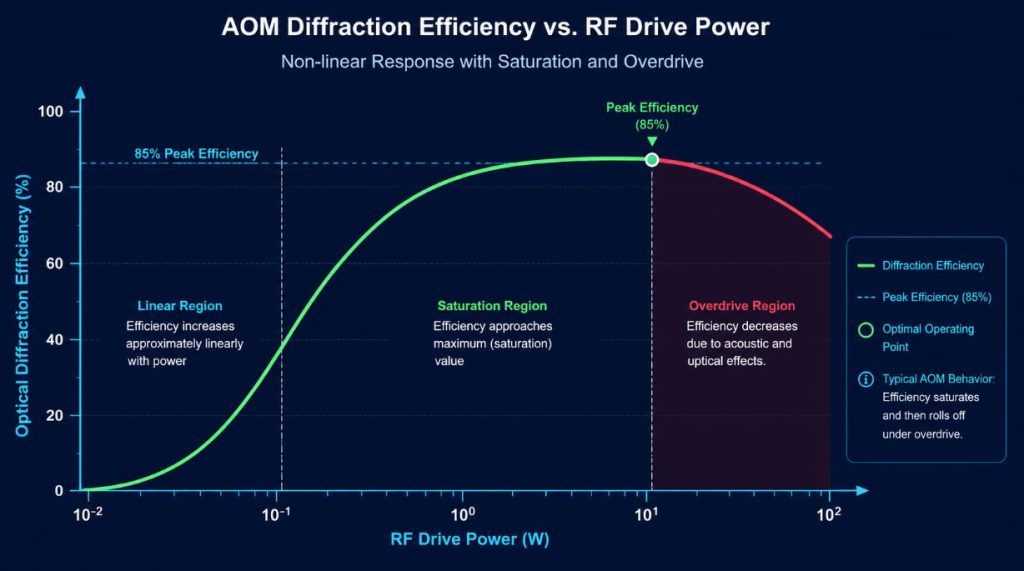
When the Bragg conditions are met, the incident light undergoes deflection and forms a first-order diffraction beam. In the Bragg region, the diffraction efficiency is in a sinusoidal square relationship with the acoustic power, exhibiting a clear nonlinearity:
- Linear region: At low RF power levels, the intensity of the first-order diffraction light increases proportionally with the increase in power.
- Saturation peak: As the RF power increases, the efficiency curve flattens out and reaches a peak (for fiber-optic devices, it is usually 80% – 90%).
- Over the drive region: Beyond the saturation point, the light will couple back to the zero-order or higher-order modes, resulting in a reverse decrease in diffraction efficiency.
The Downside of Overdriving Acousto-Optic Crystals
When the RF power exceeds the saturation point, the excess energy cannot be converted into diffracted photons, but instead dissipates in the form of heat within the crystal and sound-absorbing materials.
This thermal deposition causes the crystals in the compact package to heat up rapidly, resulting in severe temperature gradients and subsequently damaging the performance of the optical components.
Thermal Lensing and Beam Degradation Risks
M² Beam Quality Distortion
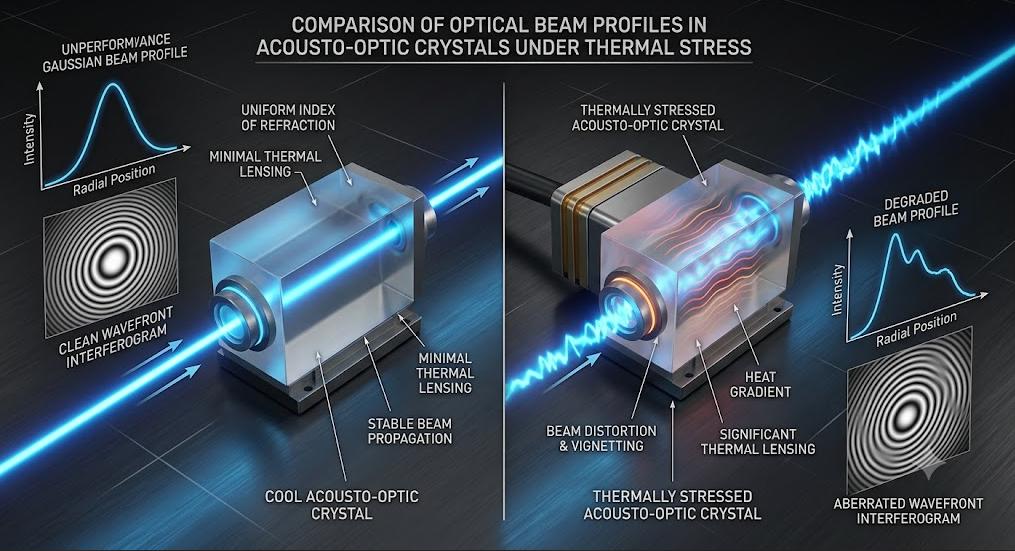
Excessive heat dissipation can cause a local temperature gradient within the light aperture of the fiber AOM. Due to the thermal sensitivity of refractive indices of materials such as TeO₂, uneven heating will induce the thermal lensing effect.
When the TEM₀₀ Gaussian beam passes through the heated AOM, it will result in:
- Wavefront phase distortion;
- The focus drifts with the dynamic variation of RF power;
- The spatial beam propagation factor (M2) will significantly decrease;
For precision laser processing or free-space coupling, degradation of beam quality will severely undermine the focusing performance and reduce the power density at the focal point.
Polarization Drift and PDL Spikes
In polarization-maintaining (PM) fiber AOMs, maintaining a high polarization extinction ratio (PER) is crucial for coherent sensing, interferometric measurements, and ultrafast pulse amplification. Excessive RF power generates heat that is conducted to the micro-optical components and the fiber alignment ring.
The thermal expansion causes asymmetric mechanical stress, resulting in:
- Birefringence change: The polarization state deviates from the original axis and rotates.
- PDL increase: Polarization-dependent loss (PDL) shows peaks, resulting in an increase in insertion loss fluctuations.
- PER significantly decreased: The polarization extinction ratio dropped from >20 dB to a single digit, causing system amplitude instability.
Thermal Stress and Crystal Damage
In high-power applications (such as 1064 nm industrial fiber lasers with an average power of several watts), the combination of high light intensity and RF thermal load can lead to intense local heating.
Thermal stress can cause the bonding layer of piezoelectric transducers to delaminate, the crystal coating to deteriorate, and even lead to catastrophic thermal fractures in the acoustic-optic medium.
Step-by-Step: Finding the AOM Saturation Point
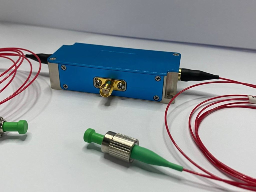
To achieve the maximum diffraction efficiency without causing thermal degradation, engineers can determine the “inflection point” of radio frequency saturation through controlled experiments.
1. Build the optical diagnostic loop
Connect the laser source to the input tail fiber of the optical fiber AOM, and connect the output of the first diffraction to the optical power meter. Connect the adjustable RF driver to the input port of the AOM to ensure that the RF connection is matched to 50 ohms.
2. Draw the RF power vs. efficiency curve
Start from 0 RF power, gradually increase the RF driver output power by small increments (such as 0.1 W or 0.5 dBm). At each increment node, record the RF input power and the output light power of the first diffraction.
Diffraction efficiency (%) = (First-stage output power ÷ Net input power) × 100%. Plot a function curve with RF power as the abscissa and diffraction efficiency as the ordinate.
3. Lock the inflection point and reserve a 10% thermal margin
As the RF power increases, the efficiency curve rises gradually and then levels off.
- Determine the saturation peak: Identify the exact RF power corresponding to the maximum diffraction efficiency.
- Apply the 10% margin rule: Reduce the RF driving power to 5% – 10% lower than the absolute peak.
Operating slightly below the peak power can reduce the RF thermal load by 15%–20%, while the loss in optical diffraction efficiency is only 1%–2%. This operating margin ensures that the AOM maintains thermal stability during continuous wave (CW) operation or long duty cycle cycling.
Engineering Checklist: RF Driver and Thermal Selection
When selecting the RF driver for the optical fiber AOM and designing the heat dissipation housing, the following five system-level integration parameters need to be verified:
- Impedance matching and VSWR stability: Ensure that the driver maintains an output impedance of 50 ohms and the VSWR is less than 1.2:1. High RF reflections will feed back thermal energy to the driver and transducer, causing power drift.
- Heat dissipation and structural thermal conduction: Create a low thermal resistance path by directly fastening the AOM chassis to the copper/aluminum heat sink using high-performance thermal interface materials (TIM).
- RF power flatness and harmonic distortion: Select a driver with a full-band RF output flatness of less than ±0.5 dB. High harmonic distortion will convert electrical energy into parasitic frequencies, deteriorating beam quality.
- Active thermal control of the phase-sensitive loop: For applications such as interferometry or quantum sensing, an integrated thermoelectric cooler (TEC) or active temperature measurement is employed to prevent thermal expansion from reducing the polarization extinction ratio (PER).
- Pulse laser driver duty cycle protection: Ensure that the driver has peak/average power limitation and rapid blanking functions to prevent local thermal spikes in high duty cycle Q switches or burst mode.
This way, there won’t be any garbled characters when copying! Please send the next paragraph. I will also pay attention to using only plain text display symbols in the following messages.
Final
The performance of the optical fiber AOM depends on precise power management rather than the maximum driving power. Bragg diffraction follows a nonlinear saturation curve. Exceeding the saturation point will result in thermal lensing, polarization drift, and beam degradation.
By plotting the “RF power – diffraction efficiency” curve and setting the driving power slightly below the saturation peak, thermal instability can be effectively avoided. Combined with a well-calibrated RF driver and a conductive heat dissipation design, the fiber AOM can achieve high diffraction efficiency, high-quality beams, and long-term reliability in high-demand laser, sensing, and communication applications.