
Troubleshooting FAQ: Why is Your Fiber AOM Extinction Ratio Degrading Over Time?
In high-precision optical systems (such as coherent Doppler lidar, distributed optical sensing DAS/DVS, and ultrafast pulse amplification), the extinction ratio (ER) of the fiber acoustic-optic modulator (Fiber AOM) directly determines the signal-to-noise ratio and pulse purity of the system.
However, in actual operation, an optical fiber AOM that performed perfectly during a certain benchmark period often experiences degradation of the extinction ratio after continuous operation for several months. This degradation can cause light leakage in the modulator when it is “off”, thereby raising the noise baseline of the system. The decline in extinction ratio is rarely attributed to the failure of a single component; it is usually the result of the interplay and evolution of optical, electrical, and thermal environmental factors. This article will analyze the four core causes of extinction ratio degradation and provide a systematic troubleshooting process to help you locate and solve performance degradation issues.
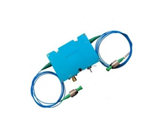
Core Analysis: Why Does the Extinction Ratio Degrade?
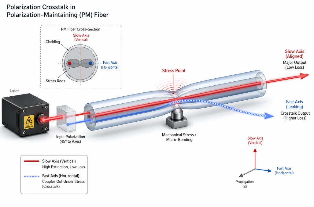
Polarization Crosstalk and PER Degradation
To ensure that the polarization-maintaining optical acoustic modulator (PM AOM) has a high extinction ratio, it is necessary for the input light polarization state to be absolutely aligned with the slow axis of the optical fiber. However, in actual operation, environmental changes will gradually disrupt this balance.
On one hand, mechanical stress caused by micro-bending of the optical fiber jumper, physical displacement, or overly tight cable ties can lead to local birefringence. On the other hand, thermal expansion due to temperature fluctuations at room temperature can also alter the microscopic structure of the coupling connector. When these factors cause the extinction ratio of the incident light polarization to decrease or result in axial misalignment, some photons will propagate along the fast axis. Since this portion of cross-polarized light cannot match the Bragg diffraction conditions within the crystal, it will directly leak to the output port in the off-state, leading to a sharp deterioration in the overall extinction ratio.
RF Driver Instability and Impedance Mismatch
As an active device, the fiber acousto-optic modulator (AOM) completely controls the “on” and “off” states of the optical signal via RF (Radio Frequency) power. To achieve a perfect “off” state (i.e., an extremely high extinction ratio ER), the key lies in ensuring that no acoustic waves remain inside the acousto-optic crystal when the RF signal is turned off.
- RF power leakage: During long-term operation, the RF driver will be affected by thermal stress, causing the internal switching transistors, isolation circuits, and other components to gradually age. This aging will result in RF power leakage during turn-off. Even if there are only a few milliwatts of residual power, it is sufficient to excite weak sound waves in the crystal and cause diffraction, causing the optical signal to leak to the output end.
- Impedance drift: Continuous thermal cycling will alter the impedance of the RF cable, SMA connector, and transducer matching network. When impedance mismatch occurs, the RF signal will undergo reflection, thereby causing distortion in the driving waveform. This not only reduces the diffraction efficiency in the “on” state but also undermines the gate control accuracy required for a high extinction ratio.
Thermal Effects and Opto-Thermal Absorption
When optical-acoustic crystals (such as TeO₂or SiO₂) are in operation, they inevitably absorb a small amount of light energy and high-power radio frequency (RF) driving energy. When the acoustic-optical modulator (AOM) is exposed to a high-load environment – such as processing watt-level 1550 nm lasers or high-power 532 nm green light – if the external heat dissipation design is not ideal, local thermal gradients will form within the crystal. This thermal distortion not only causes the thermal lens effect but also leads to uneven refractive index distribution within the optical aperture, thereby disrupting the strict Bragg diffraction matching. The ultimate consequence is that the diffraction efficiency in the on-state significantly decreases, while in the off-state, scattered light leaks into the output fiber.
Optical Damage and Fiber End-Face Contamination
The core failure mechanism usually stems from physical degradation, and it mainly occurs within the crystal or at key interfaces:
- Fiber end contamination: The core of FC/APC type fiber connectors has an extremely high power density, making it extremely sensitive to external contamination. Even in a standard laboratory environment, sub-micron-sized dust particles or volatile organic compounds (VOCs) can easily deposit on the end face. These contaminants will continuously absorb light energy and gradually carbonize, thereby scattering the unmodulated light back into the optical path.
- Crystal and coating aging: Operating for a long time under conditions close to the damage threshold of the material will cause minor physical defects in the anti-reflection (AR) coating or within the crystal. In a 532nm green light system, this high-energy exposure will also accelerate the “photo-darkening” effect of the coupled optical fiber, resulting in a sharp increase in insertion loss and scattering, directly reducing the extinction ratio (ER) of the system.
Troubleshooting Guide for Your Fiber AOM System
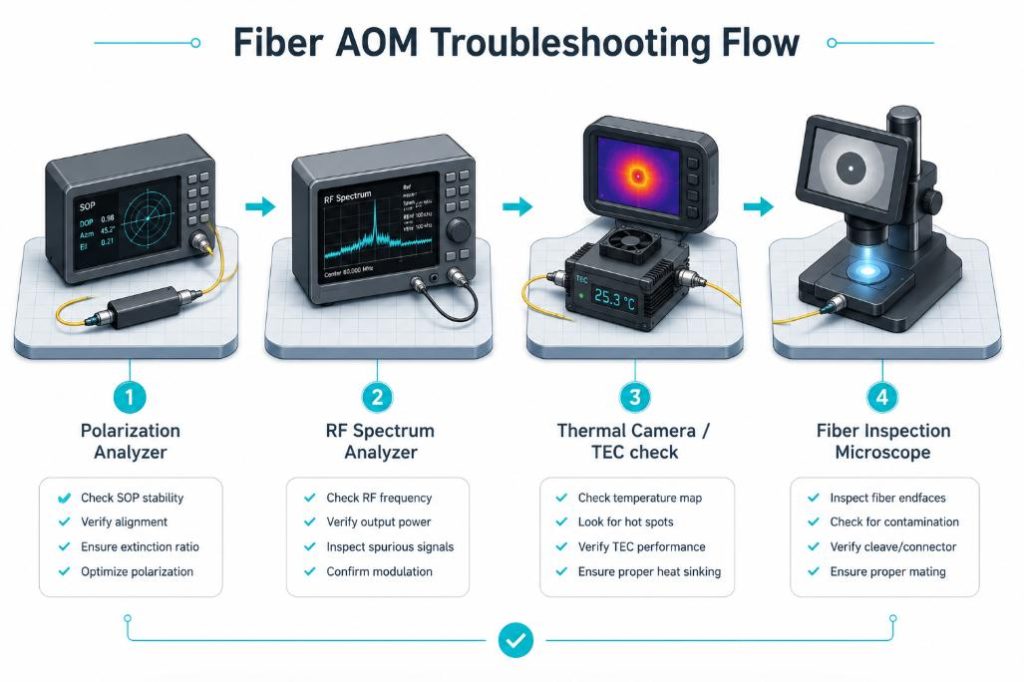
If the extinction ratio (ER) of the system drops, you can try to identify and solve the problem by focusing on the following key steps:
1. Verify the polarization state of the incident light
First, disconnect the input end of the AOM and directly measure the polarization extinction ratio (PER) of the incident light using a polarization analyzer. Ensure that this indicator meets the basic threshold (usually greater than 20 dB). At the same time, carefully inspect the input pipeline – too small a fiber bending radius or overly tight cable ties can cause stress, thereby disrupting the polarization state.
2. Check RF Driver Off-State Leakage
Connect the output of the RF driver to an RF power meter or spectrum analyzer. When the driver is switched to the “off” state, check for any remaining RF power output. Ideally, this power should be suppressed within the range specified by the manufacturer (typically below -40 dBm, depending on the model specifications).
3. Monitoring Thermal Performance and Temperature Rise
Thermal drift is a common cause of degradation in extinction ratio. It is recommended to record the initial extinction ratio (ER) immediately after a cold start and conduct continuous monitoring for 30 to 60 minutes during high-power operation. If the extinction ratio only decreases significantly after the device heats, it is necessary to focus on checking the thermal interface material (TIM) between the AOM housing and the optical platform, or confirm whether the TEC (thermoelectric cooler) feedback loop is functioning properly.
4. Inspect and Clean Fiber Connectors
Damaged end faces can cause scattering. Use a high-resolution fiber microscope to carefully examine the end faces of the input and output connectors. Check for any pits, burn marks, or dust contamination. If there is any dirt, clean it with specialized fiber-cleaning paper and high-purity isopropyl alcohol (IPA). Recheck the results before reattaching for testing.
To Summary
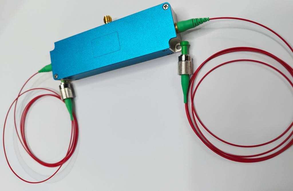
The degradation of the extinction ratio of an optical fiber acousto-optic modulator (AOM) is not an instantaneous process. Environmental fluctuations, device aging, or poor heat dissipation can all play a role in this gradual deterioration. To ensure its long-term stability, the key lies in the details: the input polarization direction must be precisely aligned, and excessive tension should be avoided during fiber routing. At the same time, the heat dissipation of the modulator and the RF driver also needs to be kept up.
As long as you pay more attention in your daily work – such as regularly cleaning the end faces and closely monitoring the stability of the RF power – the lifespan of the device will naturally be extended. If all these peripheral tasks are done properly, but the extinction ratio still fails to meet the requirements, the internal crystal optical components or coatings have likely suffered irreversible damage. At this point, apart from replacing the device with a new one or upgrading to more durable hardware, there may be no better solution.