Ultra-high/Ultra-low Frequency Shift Scheme
An acousto-optic frequency shifter is a device used for frequency shifting. The commonly used shift frequency is 80MHz, 150MHz, 200MHz, and so on. When the shift frequency is higher than 400MHz or less than 10MHz, the ordinary frequency shifter cannot be achieved. When higher or lower frequency shifts are needed, two acoustooptic frequency shifters can be used in parallel or series, as shown in Figure 1. In this scheme, our company has launched a homogeneous dual channel acoustooptic driver that can simultaneously output two RF signals. It is suitable for audio optical frequency shifters or broadband frequency shifter products that output two channels of the same source oscillation. The output frequency is broadband adjustable and stable, with high-temperature stability and reliability, and has a differential frequency detection port.
In the following, two optical fiber acousto-optic modulators (AOM) in series are used as an example to introduce the schemes of ultra-high and ultra-low frequency shifts. The on-off extinction ratio of the optical signal obtained by the series method is more than 100dB, which is suitable for weak signal detection.
series-connection-(b)parallel-connection-1024x633.jpg)
1. Ultra-low Frequency Shift Scheme (≤5 MHz)
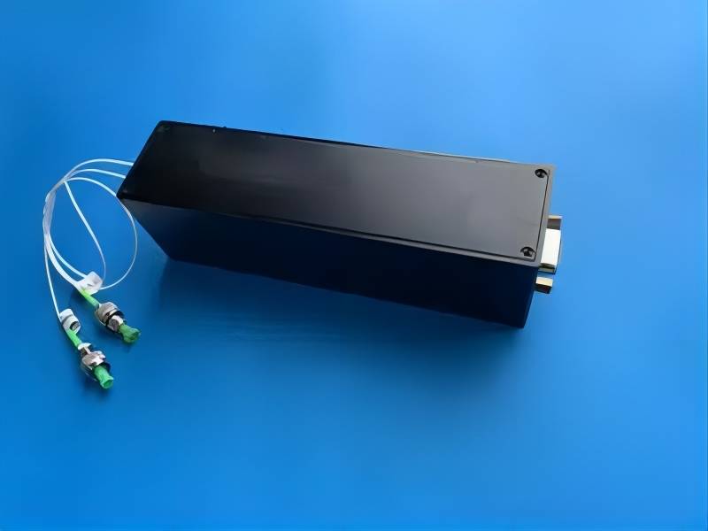
AOM1 model: SGTF80-1550-1P
AOM2 model: SGTF80-1550-1P(-)
Homogeneous dual-channel acoustooptic driver model: SGT80&80/85-33-Q1-1
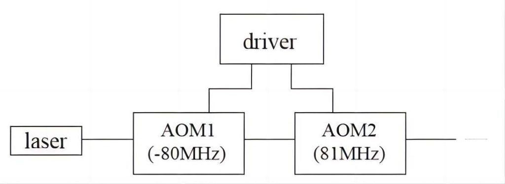
Adjust the RF output frequency of the homogeneous dual-channel acoustooptic driver to 80MHz and 81MHz (80-85MHz optional), connect the AOM to the RF input terminal, and then connect the two AOM in series, the first AOM has a negative frequency shift of 80MHz, and the second AOM has a positive frequency shift of 81MHz (80-85MHz optional). Relative to the light source, the optical fiber output will get a frequency shift of 1MHz (0-5MHz optional) optical signal. The optical path is shown in Figure 2.
2. Ultra-high Frequency Shift Scheme
AOM1 model: SGTF200-1550-1P
AOM2 model: SGTF200-1550-1P
Homogeneous dual channel acoustooptic driver model: SGT200&190/200-33-Q1-1
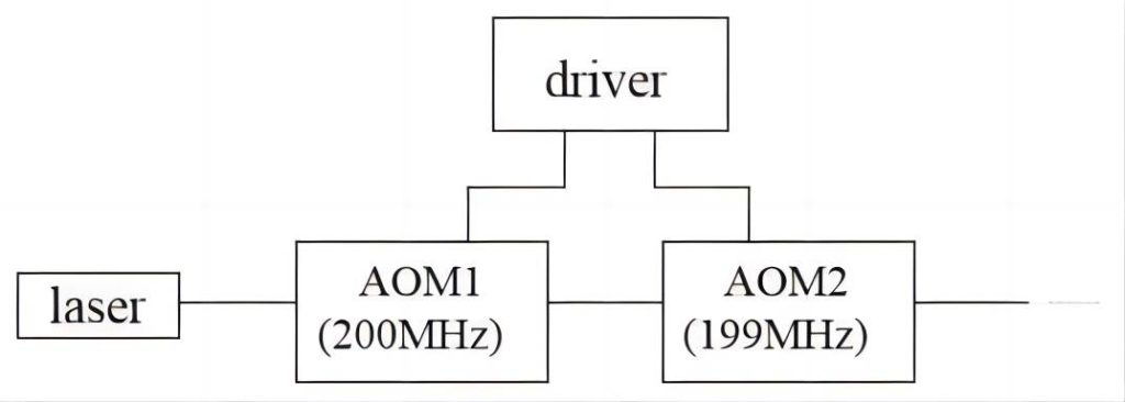
The RF output frequency of the homogeneous dual channel acoustooptic driver is adjusted to 200MHz and 199MHz respectively (190-200MHz is optional), and the two AOM are connected to the RF input terminal of AOM, and then the two AOM are connected in series. The first AOM has a positive frequency shift of 200MHz. The second AOM has a positive frequency shift of 199MHz (190-200MHz optional), and compared to the light source, the optical fiber output will get a frequency shift of 399MHz (390-400MHz optional). The optical path is shown in Figure 3.
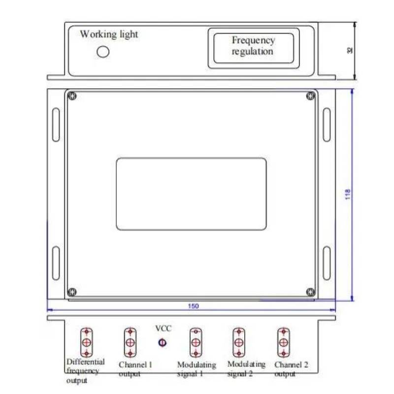
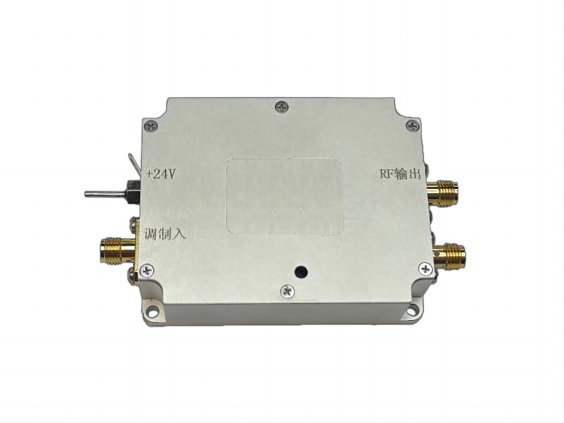
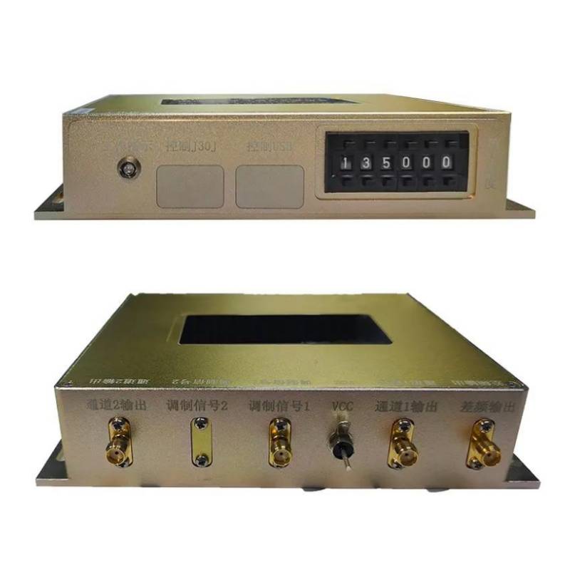
The shape structure of the homogeneous dual channel acoustooptic driver is shown in Figure 4. One side of the driver has a working indicator and a frequency adjustment port (button adjustment), and the other side of the driver has a difference frequency output port, two modulation signal input ports, two RF output ports, and a power interface (capacitor). The optical signal is modulated by applying a digital or analog signal. One RF output port is a fixed frequency output and the other is a frequency adjustable output. The frequency adjustment port is a 6-bit button, and the frequency adjustment step changes with the driver model and can be as small as the Hz level (customized), which brings more choices for users. Figure 5 shows the physical image of the homogeneous dual channel acoustooptic driver.