
What is the Rise Time of a Free-Space AOM and How Can You Optimize It?
In applications such as ultrafast laser modulation, pulse selection, and high-speed optical switches, the response speed of the acoustic-optic modulator (AOM) determines the performance limit of the entire system. Some common problems that engineers encounter on optical platforms are issues such as pulse truncation, signal overlap, or inability to reach the switching speed specified in the data sheet of the AOM.
To solve the problem of slow response speed, it is not necessarily necessary to purchase new components. Instead, you only need to understand the physical variables that affect the rise time of the AOM (that is, the time required for the modulation light output intensity to rise from 10% to 90%).
By adjusting the beam geometry and understanding crystal mechanics, you can optimize the rise time of the free-space AOM to the nanosecond level without increasing the budget.
What Actually Determines AOM Rise Time?
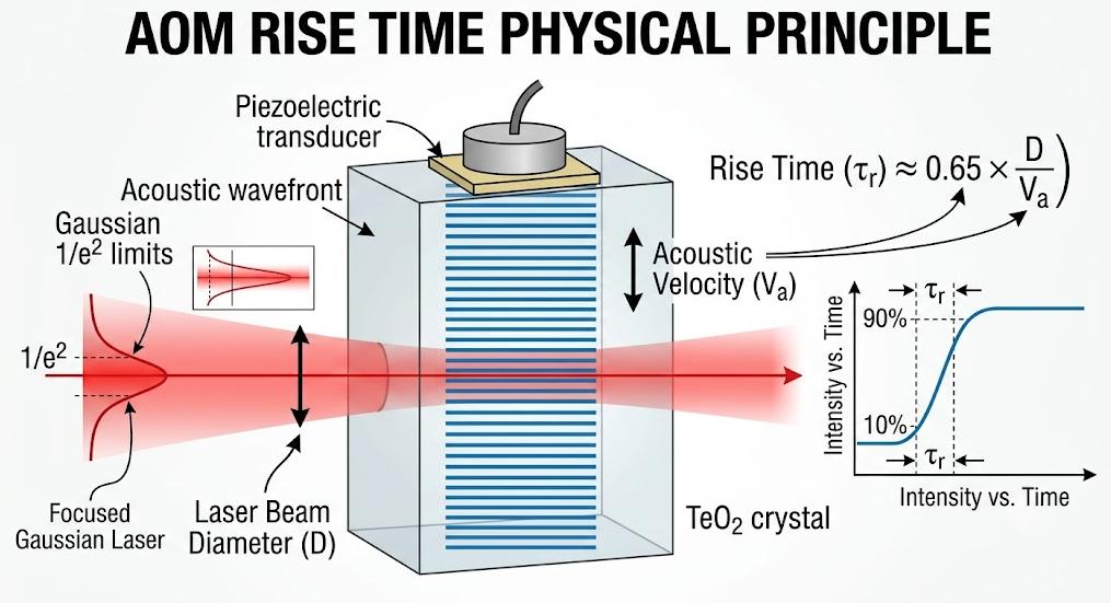
A frequent misconception in laser laboratory environments is that an AOM’s rise time is dictated solely by the electronic switching speed of its RF driver. While RF driver performance sets a baseline, the true physical bottleneck is the acoustic transit time within the acousto-optic crystal.
An AOM operates via the acousto-optic effect. When an RF signal is applied to the piezoelectric transducer bonded to the crystal, it generates a traveling acoustic wave. This wave creates a periodic refractive index grating via the photoelastic effect. The laser beam is modulated only when the acoustic wavefront propagates along the light’s physical path.
Therefore, the optical rise time is directly proportional to the time it takes for the sound wave to traverse the laser beam profile. It is mathematically defined by the standard Gaussian beam approximation:
Rise Time = 0.65 x (D / Va)
Where:
- D is the 1/e^2 laser beam diameter inside the crystal.
- Va is the acoustic velocity of the specific crystal material (for example, approximately 4200 meters per second for Tellurium Dioxide, TeO2, longitudinal mode).
The formula reveals a fundamental truth: the larger your laser beam diameter at the interaction zone, the slower your rise time will be. If your beam diameter is 1 mm in a TeO2 crystal, your rise time will hover around 150 ns. To achieve a 15 ns rise time, that beam diameter must be scaled down to roughly 100 microns.
How to Optimize Free-Space AOM Rise Time: 3 Practical Steps
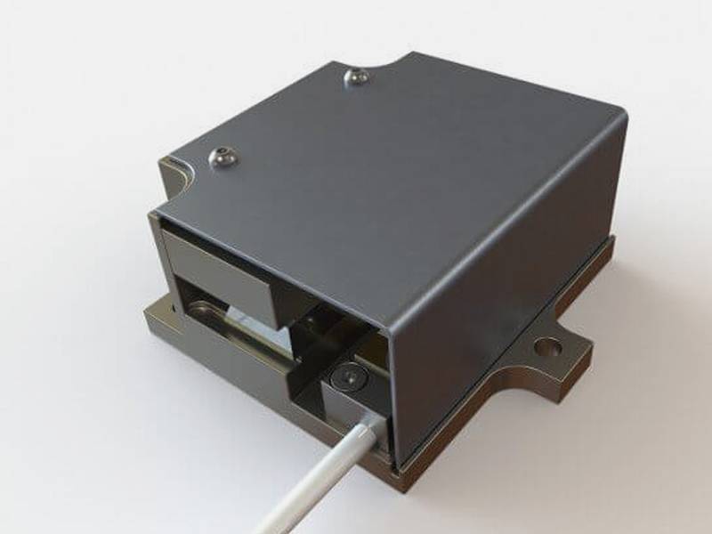
If your current bench setup is yielding sluggish rise times, implement these three sequential engineering adjustments.
1. Focus the Laser Beam (The Geometric Factor)
Since beam diameter D is the dominant variable, reducing it via external optics yields the most drastic speed improvements.
To achieve this, configure a lens pair to focus the laser beam precisely inside the AOM crystal, and then recollimate it afterward.
Incoming Beam —-> [ Focusing Lens ] —-> ( Focal Spot inside AOM Crystal ) —-> [ Collimating Lens ] —-> Optimized Output
When calculating your focusing optics, use the target waist diameter formula:
D_waist = (4 x wavelength x f) / (pi x D_in)
Where f is the focal length of the lens, and D_in is the input beam diameter.
Critical Safety Threshold: While focusing increases speed, it also spikes the local power density (W/cm^2). You must cross-reference your calculated focal spot size with the manufacturer’s specified Laser Damage Threshold (LDT) for the crystal and anti-reflective (AR) coatings. Tight focusing of a high-power or nanosecond pulsed laser will cause catastrophic thermal fracturing of the crystal facet.
2. Position the Beam Close to the Transducer (The Spatial Factor)
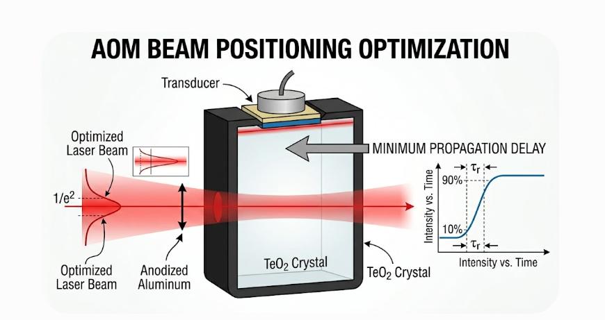
During the process of sound waves traveling away from the piezoelectric transducer, they do not always maintain a perfect plane; they will be affected by sound diffraction, attenuation, and the deviation of the sound waves.
To obtain the clearest and most coherent sound wave front:
- Install the free-space acoustic-optical modulator (AOM) on a precision kinematics or translation stage.
- Carefully move the AOM in the direction perpendicular to the path of the light beam, so that the laser is as close as possible to the surface of the transducer, but do not touch the internal aperture housing.
By minimizing this distance to the greatest extent, the delay and jitter in the propagation of sound waves can be eliminated, ensuring that the rising edge of the sound wave reaching the photon path is as steep as possible, thus reaching the limit allowed by crystal physics.
3. Match the RF Driver Impedance & Rise Time (The Electrical Factor)
If your optical geometric structure is flawless, but the rise time is still very slow, then the bottleneck might be the RF transmission network.
Check impedance matching
Ensure that the RF cables, connectors, and driver outputs are strictly matched to the internal transducer impedance of the acoustic-optical modulator (AOM) (typically 50 ohms). If there is a mismatch, it will result in voltage standing wave reflection (VSWR), which will blur the electrical rise edge and cause pulse trailing.
Evaluate the rise time of the drive
It is confirmed that the inherent electronic rise time of the RF driver is significantly faster than the target optical rise time. The total rise time of the system is proportional to the square root of the sum of squares:
Total rise time = √[(optical rise time)² + (driver rise time)²]
Try to minimize the length of the RF cable as much as possible to eliminate parasitic capacitance.
How Crystal Selection Affects Speed?
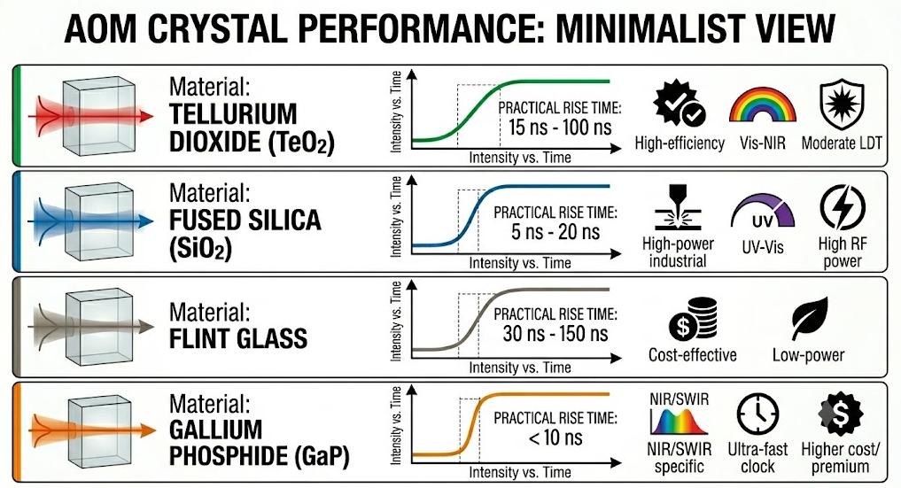
If you have tried all the optical alignment techniques but still cannot meet the rise time requirements, then the choice of the crystal material might be the limiting factor. Different crystals have different sound velocities (Va), and this determines the maximum speed of the device.
| Crystal Material | Practical Rise Time Range | Primary Application Considerations |
| Tellurium Dioxide (TeO2) | 15 ns – 100 ns | High diffraction efficiency; standard choice for visible to NIR wavelengths; moderate Laser Damage Threshold (LDT). |
| Fused Silica (SiO2) | 5 ns – 20 ns | Excellent for high-power industrial lasers and UV applications; requires much higher RF drive power. |
| Flint Glass | 30 ns – 150 ns | Cost-effective for low-power acousto-optic applications; limited velocity. |
| Gallium Phosphide (GaP) | < 10 ns | Exceptional velocity for NIR/SWIR; ideal for ultra-high-speed processing but higher cost. |
When designing a system from scratch and if a speed of 10 ns or lower is required, then fused quartz or gallium phosphide crystals should be chosen. If you need to achieve the maximum luminous flux and diffraction efficiency at the standard industrial power level, as long as the correct focusing configuration is adopted, tellurium dioxide (TeO2) remains the industry standard.
Conclusion
In simple terms, optimizing the rise time of the free-space acoustic-optic modulator (AOM) requires a trade-off between the beam diameter, material limitations, and damage threshold. By focusing the laser beam to the extent that meets the speed requirements, while ensuring that the power limit of the crystal is met, and positioning the beam near the transducer surface, the nanosecond-level peak performance promised in the device data sheet can be achieved.