
Why Optical Passive Devices Fail in Long-Term Deployment? And How Strict QA Prevents It
In optical networks, ultrafast fiber lasers, and quantum photonics systems, passive components operate without power and are often assumed to possess high reliability.
However, during long-term operation, passive components such as optical delay lines, acousto-optic devices, couplers, and isolators are prone to performance degradation. After 6 to 12 months of deployment, increased insertion loss (IL) or decreased polarization extinction ratio (PER) can lead to signal distortion, system downtime, and high field maintenance costs.
Analyzing the causes of long-term failures in passive components and implementing rigorous quality control (QA) are crucial for ensuring the long-term stable operation of optical systems.
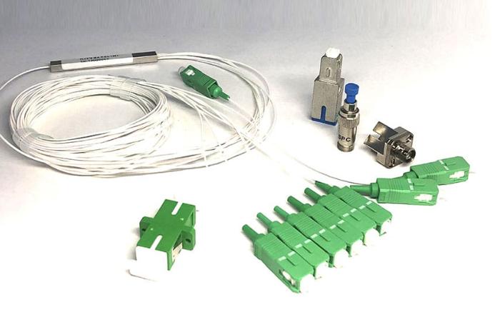
The 4 Core Root Causes of Long-Term Passive Device Failures
Unlike active devices which fail due to semiconductor wear or electrical breakdown, the degradation of passive optical devices mainly results from microscopic mechanical displacement, environmental influences, and material aging.
Epoxy Degradation & Thermal Outgassing
Passive components often use epoxy resin and optical adhesives to fix optical fibers, lenses and crystals. Under long-term thermal cycling, temperature fluctuations or high light power, poor adhesives will undergo chemical aging, leading to the following risks:
- Optical yellowing: The glue changes color and thickens, directly increasing insertion loss (IL).
- Thermal release gas: Volatile organic compounds escape from uncurdled or low-grade adhesives and deposit on the optical end face or crystal surface.
Over time, these tiny pollutants will absorb light, creating localized hotspots and accelerating catastrophic optical damage.
Internal Stress Relaxation & Alignment Drift
Low insertion loss and high polarization extinction ratio (PER) depend on the nanoscale alignment between the core, the polarization-maintaining optical fiber and the crystal. Residual mechanical stresses generated during assembly, cutting or curing will slowly be released over the long term, causing sub-micron-level micro-shifts in the optical interface. This offset will lead to a significant decrease in PER, power fluctuations and polarization crosstalk.
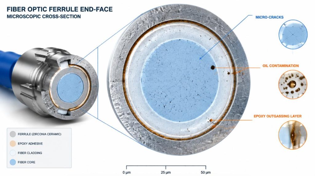
Micro-Fractures & End-Face Contamination
The damage beneath the polished surface is the main cause of component failure. Microcracks at the fiber end face are difficult to detect through routine inspections, but they will gradually expand to the core under the action of thermal cycles.
Furthermore, poor sealing of the housing can allow moisture and particles to seep in. The moisture at the fiber optic interface will alter the refractive index, resulting in deterioration of the return loss (RL) and causing back reflection, which can damage the upstream laser.
Material Fatigue Under Harsh Environments
Industrial, military, and outdoor fiber optic systems are often exposed to wide temperature variations, strong vibrations, and mechanical shocks. The coefficient of thermal expansion (CTE) of materials such as quartz glass, stainless steel casings, and polymer sleeves varies.
Without a stress buffering structure, the CTE mismatch will cause cyclic bending stress to be applied to the optical fiber during temperature changes, leading to micro-bending loss, material fatigue, and even fiber fracture.
The Standard QA Checklist: How to Prevent Early Field Failures
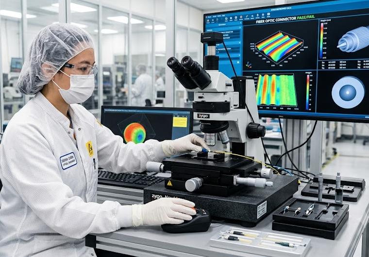
To prevent on-site failures, reliable suppliers need to implement multiple layers of quality control (QA). When purchasing and quality engineers evaluate passive component suppliers, they should focus on the following four points:
- 3D interferometer and end face inspection: The fiber end face needs to be measured by 3D interferometry to verify the radius of curvature (ROC), vertex offset, and the amount of fiber curvature (in accordance with IEC standards), ensuring physical contact and eliminating local stress.
- Temperature cycling and aging test: Conducted in accordance with Telcordia GR-1209/1221 standards for thermal shock and temperature cycling tests (-40℃ to +85℃), with pre-release of residual stress in assembly.
- High-power aging test: High-power and high-precision devices need to undergo online optical aging to promptly identify epoxy resin defects, coating absorption, and thermal lensing effects.
- Full inspection and data traceability: Before the finished products are shipped out, each one must undergo tests for insertion loss (IL), return loss (RL), polarization extinction ratio (PER), and polarization-dependent loss (PDL), and complete traceability data must be retained.
Standard vs. High-Reliability Passive Components: A Buyer’s Checklist
When purchasing passive optical components, the low initial cost often leads to high maintenance expenses, system recalibration, and the risk of on-site returns, thereby increasing the total cost of ownership (TCO).
The table below compares the core structural differences between standard commercial devices and high-reliability devices:
| Evaluation Metric | Standard Commercial Components | High-Reliability Grade Components |
| Epoxy & Adhesive Quality | Standard commercial-grade adhesive (high risk of outgassing & thermal yellowing) | Low-outgassing, space/industrial-grade optical epoxy with certified thermal curing |
| End-Face QA | Visual spot-check or batch sampling | 100% 3D Interferometer geometry and surface profiling on all units |
| Stress Relief Protocols | Basic ambient drying after assembly | Accelerated thermal cycling (-40°C to +85°C) & environmental aging pre-shipment |
| Data Traceability | Generic batch test certificates | 100% Individual serial number test report covering IL, RL, and PER |
| Long-Term Performance | Vulnerable to phase drift, IL creep, and early field degradation | Engineered for zero-defect long-term operation with stable optical specifications |
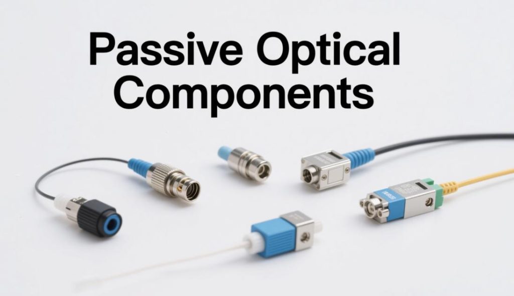
SMART SCI&TECH ’s Approach to Zero-Defect Passive Components
SMART SCI&TECH is dedicated to providing high-stability passive components for precision optical systems. Through the selection of high-quality materials, precise manufacturing processes, and comprehensive testing, we ensure that our products can operate stably for a long time in harsh environments:
- Precise assembly and stress relief: Utilizing high-precision alignment technology and low-evaporation optical adhesives, ensuring sub-micron alignment within a wide temperature range.
- 100% data traceability: Each product is tested through 3D end-face geometry, insertion loss (IL) and extinction ratio (PER), and comes with an official factory inspection report.
- Customized OEM service: Offer customization of optical delay lines and passive modules, and design packaging, interfaces and internal configurations as per requirements.
Whether you are in the prototype development stage or the mass production stage, SMART SCI&TECH can provide highly reliable passive optical components.
Visit the SMART SCI&TECH optical passive device page to obtain the complete product catalogue, or contact our engineering team for technical support and quotations.