7 Key Parameters to Check Before Buying a Variable Optical Delay Line
Aligning the optical system to sub-picosecond accuracy is notoriously demanding. Whether it’s matching the reference arm in an optical coherence tomography (OCT) device, calibrating an optical fiber interferometer, or synchronizing a high-speed transceiver test bench, variable optical delay lines are typically the preferred component for accomplishing this task.
But on paper, many delay lines seem to be the same. People often purchase a product simply based on its maximum delay range, only to find that its insertion loss peaks in the middle of the mechanical track, or that random polarization changes affect the data.
In order to avoid these performance bottlenecks after integration, you should not only rely on the basic marketing promotion, but also carefully examine the product parameters. The following seven key parameters will truly determine the performance of the variable optical delay line on the actual optical test bench.
Parameter 1: Delay Range & Resolution
Range specifies the maximum amount of optical path length change that the device will be able to accomplish, usually expressed in picoseconds (ps) or millimeters (mm). To provide an idea, one ps equals about 0.3 mm of delay in free space. Typical values can range from 0-100 ps, 0-330 ps, all the way up to 0-600 ps.
Resolution, by contrast, describes the minimum increment of delay variation that the variable optical delay line may provide, potentially reaching the sub-femtosecond (fs) or sub-picosecond level.
- Engineering Reality: Wider delays mean a longer internal mechanical track, which leads to a larger physical size of the device.
- Selection Rule: In case of high-frequency optical sampling or clock alignment, select devices offering sub-ps resolution. The delay range should not be over-specified; excess track length introduces unnecessary alignment tolerances and larger housing dimensions.
Parameter 2: Insertion Loss (IL) & IL Variation
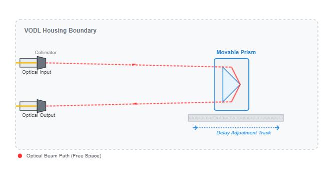
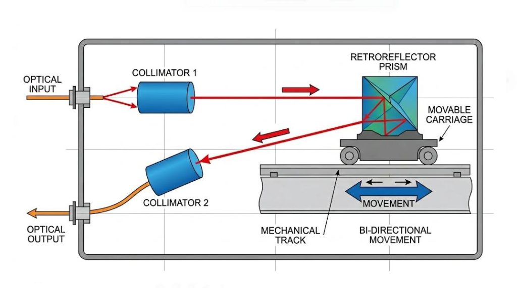
Insertion loss measures the loss of optical power when light passes through internal components (mainly starting from the input collimator, passing through free space or reflectors, and finally returning to the output collimator). A standard high-performance variable optical delay line should have an absolute insertion loss of less than 1.0 dB or 1.5 dB.
The variation in insertion loss (also known as insertion loss ripple or flatness) is equally crucial. It defines the amplitude of the fluctuation in insertion loss over the entire mechanical tuning range.
Technical risk: If there is a slight deviation in the internal alignment when the prism moves along the mechanical track, the insertion loss will fluctuate. In a dynamic testing environment or in the OCT reference arm, a significant change in the insertion loss will introduce power modulation, and the photodetector will mistakenly interpret it as signal data or noise.
Target benchmark: Search for devices that have an insertion loss variation of less than +/- 0.1 dB or less than 0.3 dB throughout the tuning range, to ensure the stability of the output power during the adjustment process.
Parameter 3: Return Loss (RL)
The return loss quantifies the optical power reflected back to the laser source and is expressed in decibels (dB). In precision laser systems, echo reflection can cause optical feedback, which makes the laser diode unstable and subsequently leads to mode hopping, phase noise and wavelength drift.
Therefore, for single-mode communication applications and ultrafast laser devices, the return loss must be greater than 50 dB or 60 dB. The design criteria are as follows: To achieve high back reflection loss, precise angle polishing (8-degree APC) of the internal fiber end face is required, and an efficient anti-reflective (AR) coating should be applied to all transmission glass-air interfaces.
Parameter 4: Wavelength Range
The optical delay line utilizes internal optical coatings optimized for specific spectral windows on the lenses and prisms. This device must be matched to the working wavelength of your light source laser.
| Application Target | Standard Center Wavelengths | Optical Fiber Standard |
| Telecom (C and L Bands) | 1530 nm to 1625 nm | SMF-28e |
| Telecom (O-Band) | 1260 nm to 1360 nm | SMF-28e |
| Medical Imaging (OCT) | 1060 nm or 1310 nm | Custom SM or PM |
| R and D / Biomedical | 850 nm | Custom / Multi-mode |
Selection rule: Operating the variable optical delay line outside the specified wavelength range will result in a sharp increase in insertion loss and a significant decrease in return loss, because the internal anti-reflection coating is unable to suppress the reflection at non-specified wavelengths.
Parameter 5: Polarization Dependent Loss (PDL)
Polarization-dependent loss (PLL) represents the maximum change in insertion loss when the polarization state of the input light changes, and is measured in decibels (dB).
- Technical risk: In a standard single-mode (SM) optical fiber system, due to the movement of the fiber and changes in environmental temperature, the polarization state will undergo random fluctuations. If the polarization-dependent loss of the variable optical delay line is high, these polarization state shifts will directly be converted into amplitude noise.
- Target benchmark: For high-speed data transmission tests (such as coherent communication), it is necessary to ensure that the polarization-dependent loss of the variable optical delay line is less than 0.1 dB. Higher polarization-dependent loss usually indicates an asymmetry in the internal optical coating or a microscopic mechanical misalignment in the collimator.
Parameter 6: Fiber Type & Connector Customization
The fibers within the connector must match your external system architecture to avoid mode-mismatch losses.
- Single Mode Fiber (SMF-28e): Standard in telecommunications and general laboratory test stations used at wavelengths of 1310 nm and 1550 nm.
- Polarization-Maintaining Fiber (PM Fiber): Necessary for systems where the polarization must be maintained precisely, including coherent receivers, fiber optic gyros, and PM interferometers. The polarization-maintaining design is generally aligned with the slow axis of the fiber.
- Connectors: Choose based on the needs of your patch panels. Preferred in applications requiring high return losses are the FC/APC connectors (angled physical contact), whereas FC/UPC (ultra physical contact) connectors will do in standard test stations.
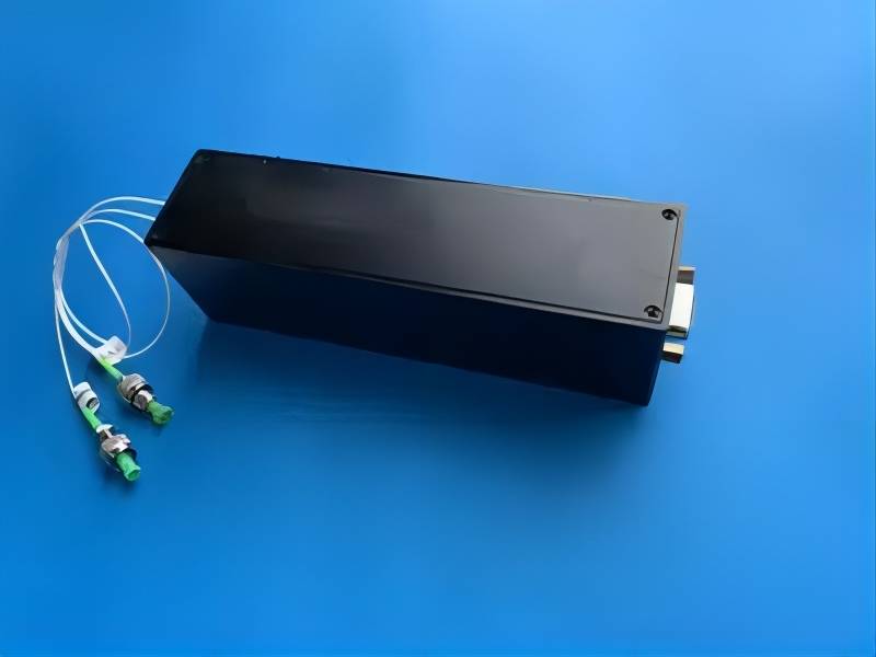
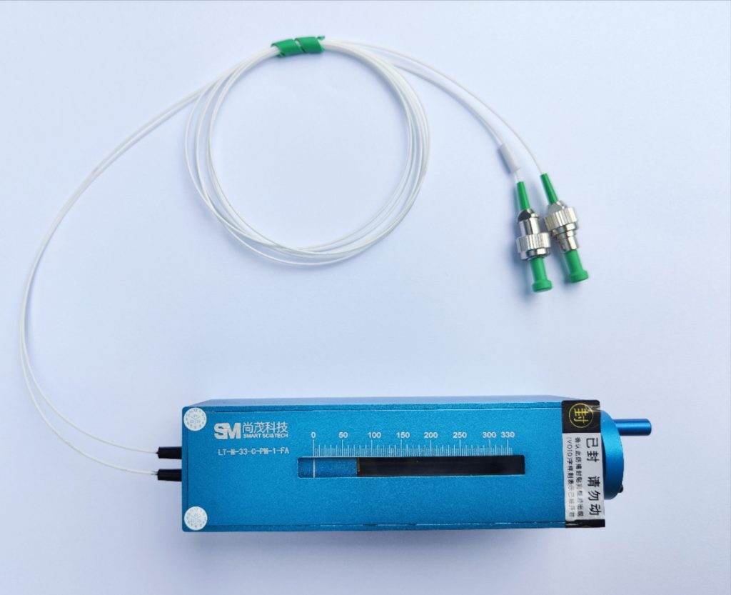
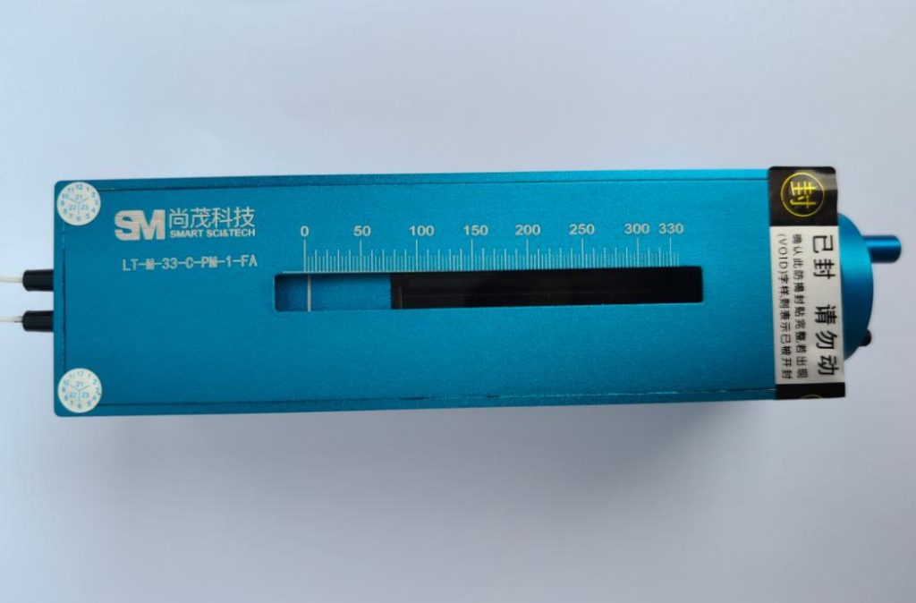
Parameter 7: Control Mode: Manual vs. Motorized
The choice whether to go for manual control or motorized control is determined purely by the type of operational environment, frequency of adjustment, and level of automation needed.
| Feature / Metric | Manual Variable Optical Delay Lines | Motorized Variable Optical Delay Lines |
| Adjustment Mechanism | High-precision micrometer drive or analog indexing dial. | Internal stepper motor or DC servo motor. |
| Control Interface | Manual physical rotation. | Software interfaces (USB, RS232, Ethernet, SPI). |
| Electrical Noise | Zero EMI (No Electromagnetic Interference); completely passive. | Potential micro-EMI from motor coils during movement. |
| Automation & Scripts | Not supported; requires human intervention. | Fully programmable via Python, LabVIEW, or C++. |
| Repeatability | Dependent on operator precision and scale reading. | Extremely high; precise step-count execution. |
| Best Application Case | “Set-and-forget” calibration, static lab benches, EMI-sensitive testing. | Automated production testing, dynamic phase tracking, high-frequency scanning. |
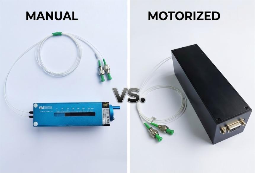
Manual Control Features:
Variable optical delays controlled manually do not come into contact with electrical noise at all, thus making them very useful in experiments that require extreme sensitivity, because they eliminate the risk of electromagnetic interference corrupting results. They are small and relatively inexpensive, making them the first option when setting up the main optical path.
Motorized Control Features:
Motorized variable optical delays have the advantage of automation and accuracy, making them very necessary in a closed-loop system that requires changes according to real-time feedback. They help integrate easily into automatic testing platforms, saving a lot of man-hours in production.
Summary and Purchasing Advice
When purchasing variable optical delay lines, evaluating the devices solely based on price or delay range may lead to system bottlenecks in other aspects. Before finalizing the Request for Quotation (RFQ), please adopt the following approach:
- Define the basic indicators: Determine your exact working wavelength and the type of optical fiber (single-mode fiber or polarization-maintaining fiber).
- Calculate the optical link budget: Ensure that the maximum insertion loss and the variation of insertion loss within the entire delay scan range do not cause your optical receiver to saturate or result in a sensitivity lower than the threshold.
- Assessing the Control Environment: If your system operates in an environment sensitive to electromagnetic interference (EMI), or if it requires a simple independent module without external power rails, choose a manually adjustable unit with a lockable micrometer to prevent drift caused by physical vibrations.
For special settings such as customized fiber length, precise polarization-maintaining fiber alignment, or ultra-low insertion loss threshold, please contact our application engineering team so that we can review your specific optical path diagram.