Bandwidth Radio Frequency Amplifier
The Bandwidth RF amplifier is a dedicated driver for acousto-optic devices, such as modulators and frequency shifters, operating within a specific frequency range and requiring less than 3 watts of power. It amplifies radio frequency (RF) signals to generate ultrasonic waves in the crystal of the device. The specific frequency and intensity of the amplified RF signal control the level of modulation, deflection, or tuning applied to the laser beam. The amplifier features efficient heat dissipation for reliable operation, and using a matched drive further enhances temperature stability for optimal performance.
Characteristics of Bandwidth Radio Frequency Amplifier
- Small size
- Fast response time
- Low power consumption
- High-temperature stability and reliability
| Supporting Drive | The SGXX/XX-33-N2-ab-Y model offers two functionalities: Y indicates its ability to shift frequencies through an external radio frequency input, while T signifies its modulation capability. The XXX represents the operating frequency, and 33 specifies the RF output power. The letter N denotes the package type. Power supply options are 24V (marked as 1) and 12V (2). Finally, D signifies digital TTL modulation capability, while A indicates analog modulation. | ||
| SGT70/90-33-N2-1D-Y SGT70/90-33-N2-1A1-Y SGT70/90-33-N2-1A5-Y | SGT100/120-33-N2-1D-Y SGT100/120-33-N2-1A1-Y SGT100/120-33-N2-1A5-Y | SGT230/270-33-N2-1D-Y SGT230/270-33-N2-1A1-Y SGT230/270-33-N2-1A5-Y | |
Ordering Information of Bandwidth Radio Frequency Amplifier
This indicator is a typical optical wavelength indicator, and other wavelengths and frequencies can be selected.
| Item | Unit | Performance | ||
| Specifications of the modulation input interface | ||||
| Modulated signal input | – | Digital modulation (high level 3.3-5V; low level 0-0.2V@1k Ω) Analog modulation (A1: 0-1V@50 Ω) Analog modulation (A5: 0-5V@1k Ω) | ||
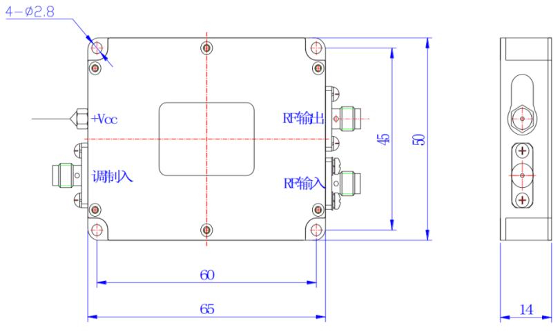
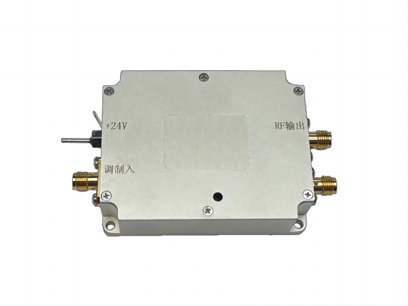
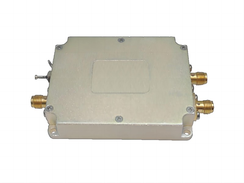
| Interface | – | SMA | ||
| RF output interface specification | ||||
| Output signal frequency range | MHz | 70-90 | 100-120 | 230-270 |
| Maximum input power | dBm | 1 | ||
| Rise and fall time | ns | <20 | <20 | <8 |
| Output signal power | W | <2 | ||
| Switching ratio | dB | ≥60 | ||
| Harmonic suppression ratio | dBc | >20 | ||
| Signal output standing wave ratio | – | ≤1.3 | ||
| Interface | – | SMA | ||
| Complete machine specification | ||||
| Gain | dB | 30±1 | ||
| Gain flatness | dB | ±1 | ||
| Maximum power consumption | W | 10 | ||
| Working voltage | Vdc | 24±1V(Optional 12±0.5) | ||
| Power interface | Through core capacitance (core wire is connected to positive, solder lug is connected to negative) | |||
| Package | – | N2 | ||