Compensating The Phase Difference Between Two Pulses Using An Optical Delay Line
In modern optical systems, phase synchronization of pulsed lasers is a key technical requirement for many applications (such as coherent beam synthesis, optical interferometry, quantum optical experiments, etc.). When there is a phase difference between two or more optical pulses, it will lead to problems such as weakened interference effect and decreased signal coherence. As a device that can precisely control the optical path, the optical delay line (ODL) can theoretically compensate for this phase difference by introducing a controllable phase delay.
Traditionally, mechanical translational delay lines achieve delay adjustment by moving mirrors to change the optical path length, while emerging electronic optical delay lines use electro-optical or acousto-optic effects to achieve faster phase control. This paper will systematically analyze the feasibility, technical limitations, and key considerations for the use of optical delay lines for phase compensation in practical applications.
Theoretical Basis For Using Optical Delay Lines To Compensate For Phase Differences
From the perspective of wave optics, the phase of light is closely related to the distance that light propagates. For light with a frequency of f, its wavelength is λ=c/f, and the phase of light changes by 2π for each wavelength of propagation. When there is a phase difference Δφ between two pulses, if the propagation distance ΔL of one of the pulses can be changed through an optical delay line so that the phase change Δφ ′ caused by the change in propagation distance is equal in magnitude and opposite in direction to the original phase difference Δφ, the phase difference can be compensated.
Assume that the frequencies of the two pulses are f1 and f2 respectively (in many practical applications, the two pulses may come from the splitting of the same light source, and the frequencies are approximately equal. Here, for general analysis, the case of different frequencies is retained), and the initial phase difference is Δφ 0. For a pulse with a frequency of f1, the optical path change ΔL introduced by the optical delay line, the corresponding phase change is:
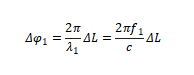
; For a pulse with a frequency of f2, its wavelength is
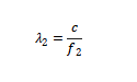
When Δφ 1=Δφ 0, the phase difference between the two pulses is compensated.
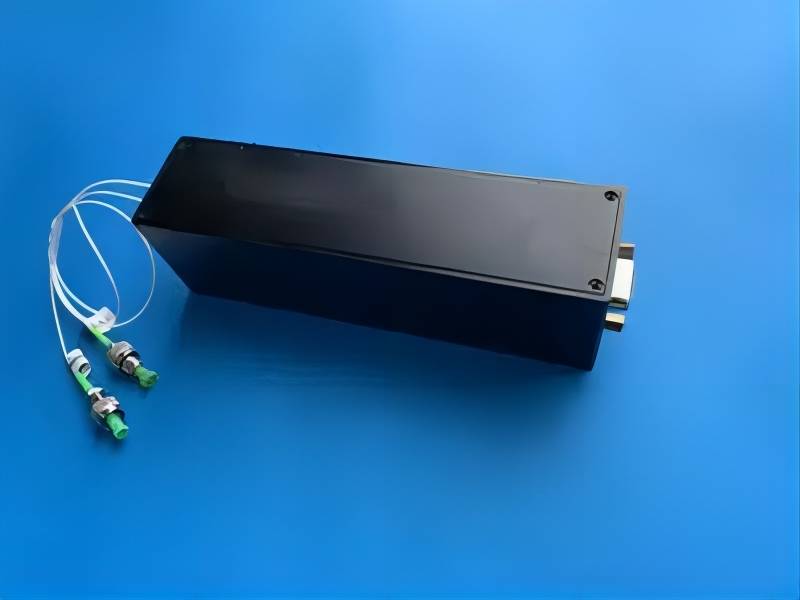
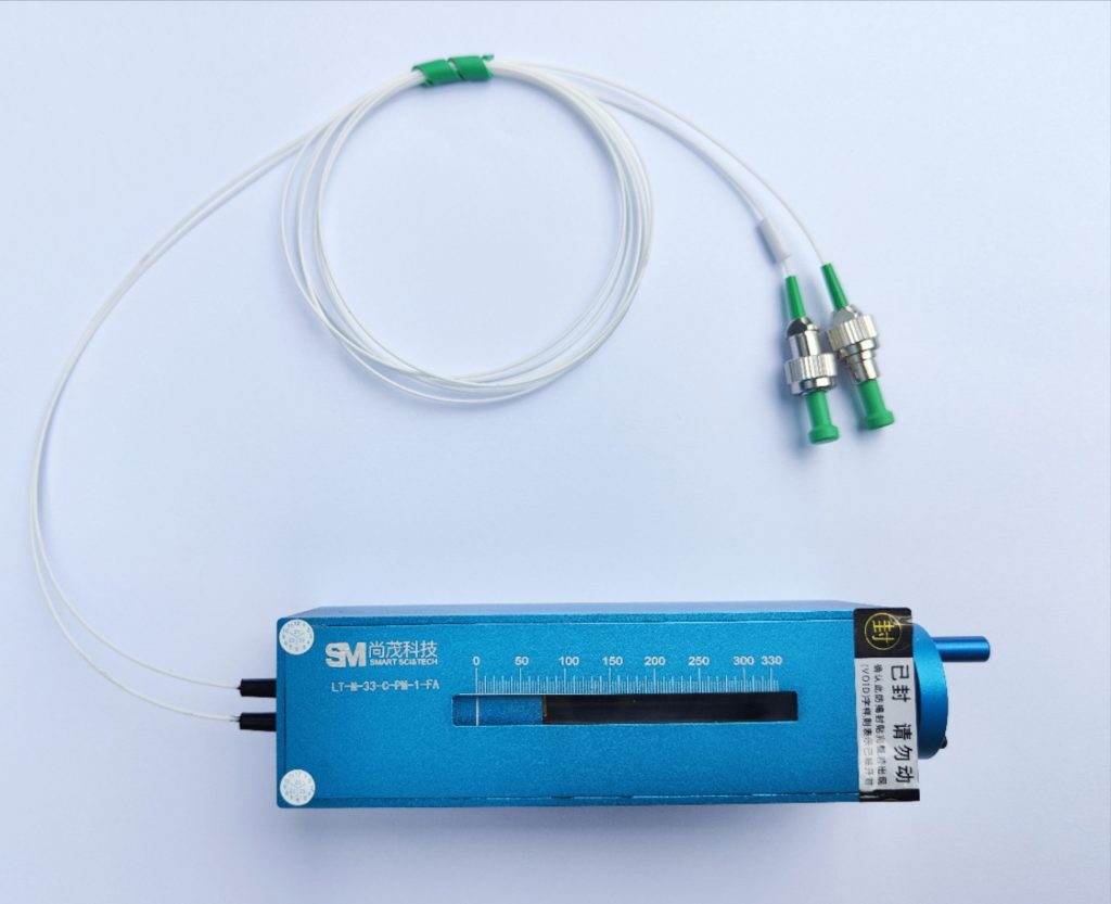
Optical Delay Lines Implementation Methods
Common optical delay line types include:
- Mechanical translation delay line: By moving the reflector through a precision displacement platform, the delay resolution can reach sub-micron level (corresponding to a phase adjustment accuracy of about 0.01λ)
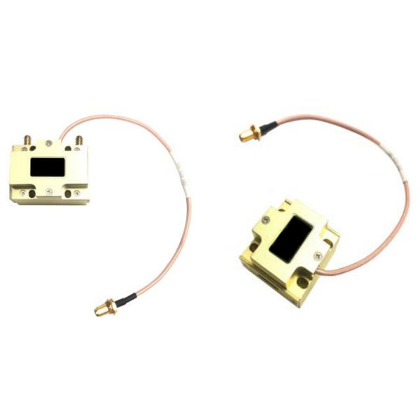
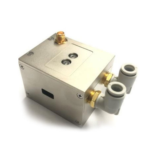
- Fiber stretching delay line: Using piezoelectric ceramics to stretch the optical fiber, ns-level delay adjustment is achieved, and the response speed is fast
- Electro-optic phase modulator: Based on the refractive index control of electro-optic crystals such as LiNbO₃, ps-level high-speed phase compensation can be achieved
- Acousto-optic tunable delay line: Control acousto-optic diffraction through RF signals to achieve programmable delay
Technical Considerations For Phase Compensation
Delay accuracy requirements
For optical pulses with a central wavelength of 1550nm, 1° phase compensation requires a delay length control accuracy of:
ΔL = (λ/360) ≈ 4.3 nm
This places extremely high demands on the stability of the mechanical system. A temperature fluctuation of 1°C may cause thermal expansion of hundreds of nm.
Dispersion effect
Things to consider when compensating broadband pulses:
Material dispersion causes inconsistent delays of different frequency components
Differences between group delay and phase delay
Pulse distortion caused by high-order dispersion
Ideal delay lines should meet group delay matching conditions:
dφ/dω = constant
Dynamic compensation capability
For time-varying phase differences, delay lines need to have:
Sufficient bandwidth (typical electro-optic modulators can reach GHz)
Fast feedback control system
Low phase noise characteristics
Limitations and Challenges of Optical Delay Lines for Phase Difference Compensation
Although optical delay lines are widely used in compensating the phase difference between two pulses, they also have some limitations and challenges. First, the delay range and accuracy of optical delay lines are limited. For optical delay lines based on fiber stretching, the stretchable fiber length is limited, resulting in a limited maximum delay range; at the same time, the nonlinear effect during the stretching process will also affect the delay accuracy. For optical delay lines based on reflectors, factors such as the mechanical movement accuracy and vibration stability of the reflectors restrict the further improvement of their delay accuracy.
Second, optical delay lines are sensitive to environmental factors. Changes in temperature will cause changes in the refractive index and length of the optical fiber, thereby affecting the delay amount of the optical delay line; in delay lines based on free-space optical paths, fluctuations in the refractive index of the air (such as those affected by factors such as temperature, air pressure, and humidity) will also interfere with the optical path, thereby affecting the accuracy of phase difference compensation. In addition, when the optical delay line is used to dynamically compensate for phase differences at high speed, its response speed may not meet the requirements of some applications. For example, in some ultra-high-speed optical communications or ultra-fast optical processes, the phase difference changes very quickly, and existing optical delay lines have difficulty tracking and compensating for this rapidly changing phase difference in real time.
Application Examples
Coherent beam synthesis
In fiber laser arrays, the use of multi-channel programmable delay lines can achieve:
- Phase locking accuracy of each channel <λ/20
- Synthesis efficiency >90%
- Applicable to kW-level high-power systems
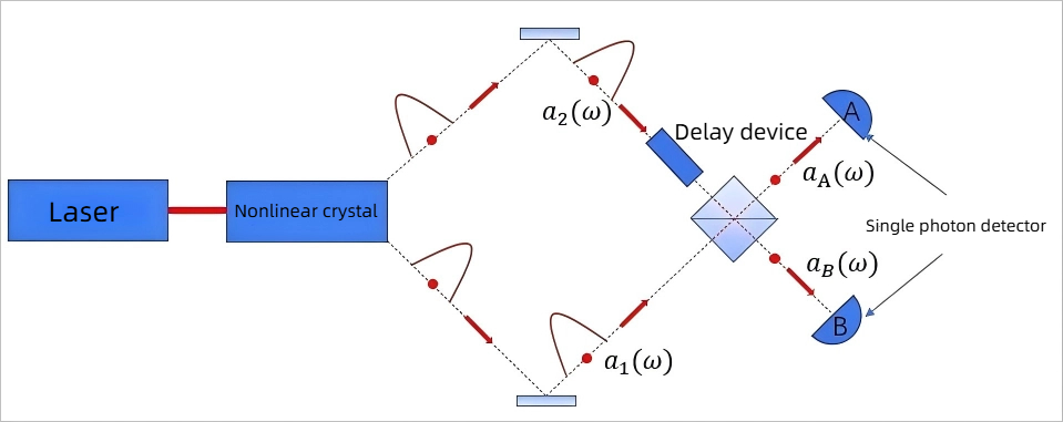
Quantum optical experiments
In Hong-Ou-Mandel interferometer experiments, delay lines are used to:
- Compensate for path asymmetry
- Adjust the position of two-photon interference
- Achieve quantum interference with visibility >98%
Summary
This paper discusses the application principle and technical implementation of optical delay lines in compensating optical pulse phase differences. By analyzing the working principle of optical delay lines, the characteristics of different types of delay lines, and the physical mechanism of phase compensation, the technical advantages and application limitations of this technology in the fields of pulse synchronization and coherent synthesis are systematically explained.
The research results show that within a specific parameter range, optical delay lines can effectively compensate for the phase difference between pulses, but their performance is subject to multiple constraints of delay accuracy, dispersion characteristics, and system stability. Modern optoelectronic hybrid delay systems combine the large dynamic range of mechanical adjustment with the high-speed response of electro-optical modulation, and can achieve phase compensation accuracy better than λ/50 in most application scenarios. Future development trends include integrated optical delay lines, machine learning optimization control algorithms, and new metamaterial delay devices, which will further expand the application potential of this technology in precision optical measurement and quantum information processing.