
Custom Fiber AOMs: Solving Dynamic PER Degradation and Jitter
When integrating an fiber acousto-optic modulator (AOM) into a high-power laser or a distributed acoustic sensing (DAS) system, an AOM with a polarization extinction ratio (PER) of 20 dB as specified in the manual may perform perfectly on a low-temperature test bench. However, when subjected to a continuous 1W or 2W radio frequency (RF) load, local thermal gradients cause the internal encapsulation materials to expand unevenly. This micro-scale structural change leads to a drop in the output PER to 13 dB within a few minutes, while introducing temporal pulse jitter. To solve such problems, custom fiber AOMs need to be designed to address the dynamic thermal-mechanical trade-offs.
Three Engineering Bottlenecks in Custom Fiber AOM Design
Misaligned Crystal Axis and Dynamic PER Degrade
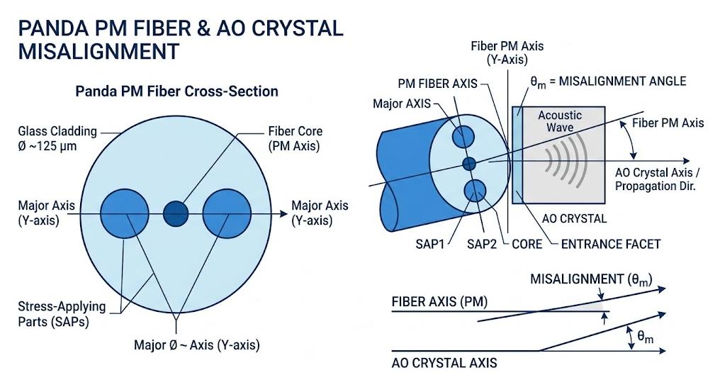
For polarization stability, an exact alignment must be established between the fast and slow axes of PM fiber pigtail and the optical axis of the acoustic crystal.
- Drawbacks of Passive Alignment Method: Panda fiber “eyes” can be aligned passively using a camera, prior to bonding them. Such an alignment method induces a 2-to-3 degree angular misalignment, limiting cold PER to less than 29 dB.
- Uneven Thermal Stress from RF: The transducer produces localized heat when operated under RF load. Using regular high thermal expansion bonding epoxy induces nonuniform thermal expansion resulting in asymmetric mechanical stress around glass-metal interface.
- Dynamic PER Drift: This asymmetric mechanical stress induces mechanical twisting in the fiber. A cold PER value of 20 dB is quickly reduced to 13 dB due to this stress.
The Trade-off: Rise Time vs. Diffraction Efficiency
High-speed pulse pickup requires an extremely short rise time, and this rise time is strictly limited by the speed at which the sound wave travels through the beam waist within the crystal (Rise time = 1.3 * beam waist diameter / sound speed).
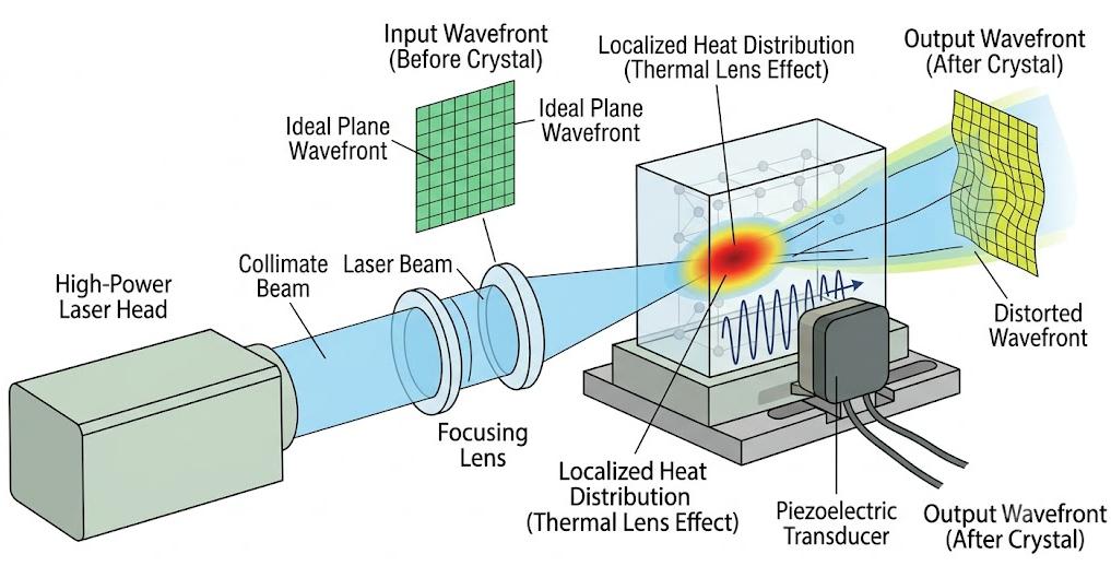
- Extremely high power density: The requirement of achieving a switching speed of less than 10 nanoseconds forces the internal lens to focus the laser beam to a beam waist diameter of less than 35 micrometers, thereby concentrating extremely high optical power into an extremely small volume.
- Thermal lensing effect: This phenomenon occurs when high power density combines with acoustic energy, creating a localized hot spot within the crystal. This hot spot causes the refractive index distribution of the material to be distorted, resulting in the curvature of the laser beam’s wavefront.
- Prague angle deviation: The curved wavefront causes the light beam to deviate from the optimal Prague angle. As a result, the diffraction efficiency drops from 85% to 70% or even lower, leading to unpredictable fluctuations in insertion loss for each pulse.
RF Impedance Mismatch (VSWR) & Signal Jitter
The piezoelectric transducer must convert the radio frequency electrical drive signal into a physical sound wave. Although the standard LC impedance matching network operates at room temperature, it will drift under dynamic thermal loads.
- High Voltage Standing Wave Ratio (VSWR): Thermal drift can cause the VSWR to soar above 1.5:1. This mismatch will force 4% to 10% of the forward radio frequency power to be reflected back, or to be dissipated in the form of waste heat on the gold electrodes.
- Sound velocity shift: This concentrated boundary heat will alter the local temperature of the crystal, thereby changing its sound velocity. Since the wavelength of a sound wave is equal to the speed divided by the radio frequency, the entire sound wave field will be subject to phase disturbances.
- Periodic noise and pulse jitter: In the time domain, these rapid phase fluctuations manifest as nanosecond-level pulse timing jitter. For high-resolution distributed acoustic sensing (DAS) or heterodyne systems, this jitter can corrupt sensor data and increase system noise.
SMART SCI&TECH Approach: Precision Engineering Metrics
SMART SCI & TECH rejects passive assembly in favor of active hardware adjustments conducted under live simulated working loads.
| Hardware Feature | Standard Assembly Limitations | SMART SCI and TECH Custom Performance |
| Dynamic PER Under Load | Drops to less than 18 dB due to epoxy expansion | Maintains 23 dB to 30 dB while running at full RF power |
| RF Impedance Control | High reflection, VSWR greater than 1.5:1 | Custom impedance tuning, keeping VSWR at 1.2:1 or lower |
| Thermal Mount Design | Standard housing paste, high thermal resistance | Indium-bonded crystal mounts with low-CTE ceramic carriers |
| Optomechanical Balance | Fixed internal beam spot size | Custom-calculated beam waists to balance rise time and thermal lensing |
Our cleanroom team uses a six-axis active optical alignment device to suppress polarization drift. During the assembly process, we operate the RF driver at full power, simultaneously injecting a real-time laser beam into the acousto-optic modulator (AOM), and adjusting the optical fiber pigtail through the electric platform until the real-time polarization crosstalk drops below -30 dB.
Furthermore, we use a low-volatility optical bonding adhesive, which has an extremely low coefficient of thermal expansion (CTE), and combine it with a soft indium foil preform for crystal installation. This reduces the thermal resistance at the interface and directly conducts the heat to the copper housing, thereby maintaining a stable sound velocity.
How to Specify Your Requirements for a High-Performance Custom AOM
In order to develop a customized device that can simultaneously take into account speed, efficiency and service life, you should define the following parameters:
- Light power distribution: Specify the average power, peak power, pulse width and repetition frequency to ensure that the damage threshold of the crystal substrate is lower than the optical damage threshold.
- Rise time and minimum efficiency: Define the priority of your system. If you require a strict 10 ns rise time, specify the minimum diffraction efficiency you can accept (for example, 75%) to guide the design of the internal lens.
- Polarization re-calibration axis: Confirm your polarization scheme. The standard calibration direction is the slow axis, but a custom scheme using the fast axis for calibration or an orthogonal 90-degree rotation configuration can also be constructed.
- Fiber encapsulation and stress relief: You can choose 250 μm bare fiber tail fibers (for compact fusion splicing), 900 μm tightly wrapped loose tubes, or reinforced stainless steel armored optical cables for harsh industrial environments.
Conclude
Standard catalog fiber AOMs struggle with polarization drift and signal instability because generic packaging cannot handle the localized heat of high-power lasers and RF drivers. Overcoming these performance drops requires optimizing internal material interfaces, managing thermal expansion variations, and ensuring precise impedance matching.
By utilizing multi-axis active alignment and custom structural thermal management, SMART SCI and TECH builds customized fiber acousto-optic modulators that deliver consistent, high extinction ratios and stable phase performance under demanding industrial and scientific operating conditions.