
How Optical Delay Line Revolutionize True Time Delay Testing in Phased Array Radar Calibration?
Switching to high-frequency bands such as X, Ku, and Ka, as well as ultra-wideband design, is fundamentally changing modern phased array radars. Whether for aerospace defense or high-resolution imaging, to enhance system performance, absolute synchronization among thousands of antenna units is essential.
For decades, traditional electronic phase shifters have been the standard for radar beam control. However, to capture finer target details and cope with complex electronic countermeasures, the radar bandwidth has been continuously expanding, which has placed severe physical limitations on the traditional electronic control architecture. The volume, thermal expansion, and power loss of traditional mechanical cables all reduce the signal quality in high-density arrays.
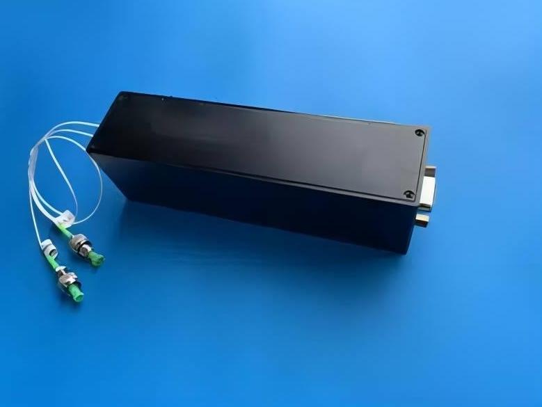
To break through these limitations, radar design is shifting towards photonics technology. By modulating radio frequency (RF) signals onto light waves, optical delay lines have been upgraded from laboratory equipment to core system-level solutions. They can provide the ultra-wideband performance, anti-interference capabilities, and high stability required for modern radar calibration.
Why Phase Shifters Fail in Wideband Phased Array Radars
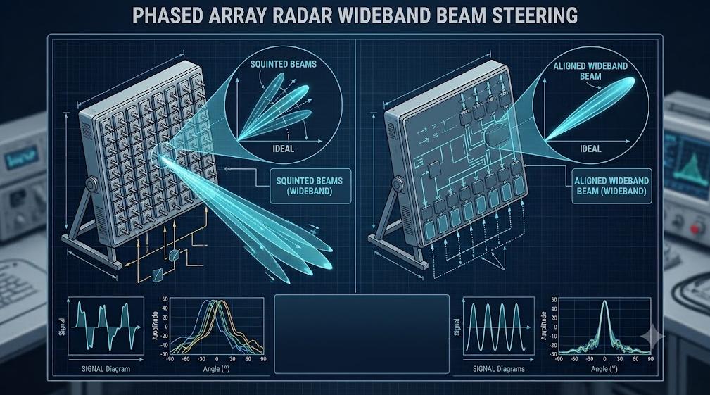
If the radar bandwidth exceeds 10%, the electronic phase shifter will introduce significant errors in beam formation. The fundamental reason lies in the physical limitation: the phase shifter only alters the phase of the signal, not its time.
The relationship between phase shift and time delay is affected by frequency:
- Phase shift is essentially bound to a specific single frequency.
- Therefore, the phase shifter can only precisely guide the radar beam at the central frequency.
When ultra-wideband pulses pass through the array, the direction angles of the high-frequency and low-frequency signals will deviate. This phenomenon is known as the beam skew effect.
It will cause the radar beam to become blurred and tilted, thereby reducing the ranging accuracy and leading to target tracking errors. If this is corrected using software algorithms, it will not only cause processing delays but also consume a large amount of computing resources.
A true broadband radar requires that the system have the same signal delay at all frequencies. This is precisely where the advantage of optical delay lines lies – they can provide true time delay (TTD) that is independent of frequency, enabling the radar beam to accurately lock onto targets throughout the entire bandwidth.
Core Applications of Optical Delay Lines in Radar Calibration Setups
Target Simulation & Echo Generation
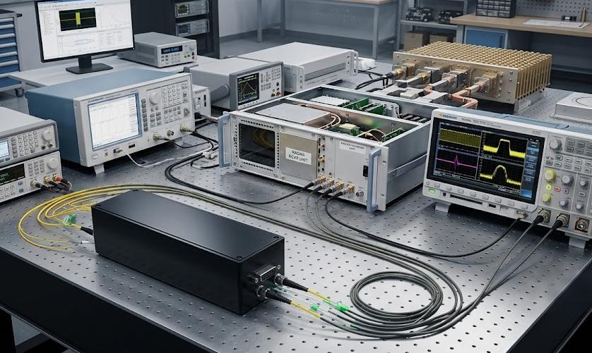
Testing a real radar is not only expensive but also subject to safety restrictions. Therefore, engineers often use “hardware-in-the-loop” (HWIL) simulation, which simulates the target echoes in the laboratory.
- During this process, the optical delay line played a crucial role.
- It converts the radio frequency pulses emitted by the radar into optical signals and precisely introduces delays of nanoseconds or microseconds through a specific optical path. This enables the direct simulation of the actual round-trip time of the target located several miles away.
Compared with traditional coaxial cables, optical fibers have extremely low signal loss, which enables them to perfectly simulate extremely long-distance targets without causing significant signal attenuation.
Antenna Array Element Phase/Delay Alignment
Large phased array radars consist of hundreds or even thousands of transceiver (T/R) modules. To achieve precise beamforming, the signal paths of each module must be completely identical. However, in reality, manufacturing errors in cables, wiring bends, and temperature changes can all lead to signal asynchrony (timing deviation).
- Therefore, this system introduces an automatic variable optical delay line as the absolute calibration standard.
- The engineer precisely adjusted each optical path, measured and compensated for the picosecond-level timing deviations.
- This ensures that the synthesized wavefront of the radar is completely undistorted.
Radar Clutter and Electronic Warfare (EW) Simulation
In electronic warfare, radars often encounter ground clutter, sea surface echoes, and enemy interference. To train radars to filter out these noises, engineers need to simulate complex environmental reflections and electronic countermeasures (ECM).
- The programmable optical delay line matrix generates complex multipath signals by separating, delaying and recombining the optical signals.
- This enables engineers to easily simulate false targets, range gate pull-out (RGPO) interference, and distributed clutter environments.
Before the hardware deployment, this solution can effectively verify the digital signal processing (DSP) algorithms of the radar for real threats.
Key Engineering Optimization Metrics for Radar-Grade Optical Delay Lines
The radar test has extremely high requirements for the optical performance of the optical delay line, far exceeding those of ordinary communication or sensing applications. This is because the fault tolerance rate of radar calibration is extremely low, and even the slightest fluctuation in the optical path can directly interfere with the radio frequency signal.
- Delay accuracy and bidirectional stability:
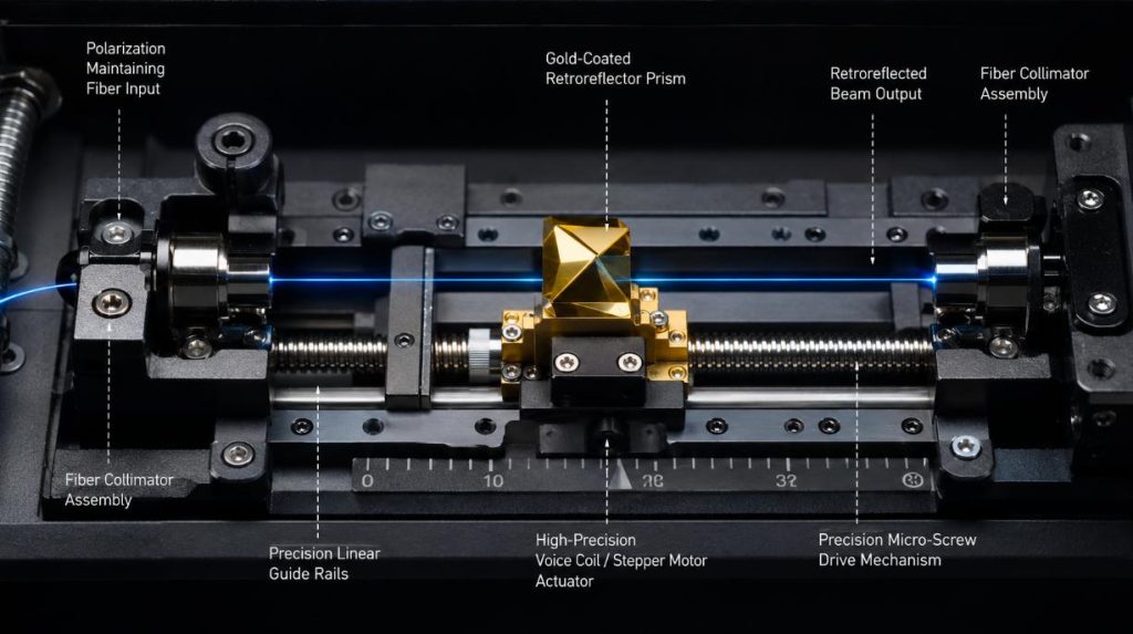
In high-frequency radar calibration (such as in the Ka band above 30 GHz), a timing error of a few picoseconds can lead to a significant phase deviation. Therefore, radar-level delay lines must achieve sub-picosecond or even femtosecond-level fine-tuning accuracy. At the same time, the system must have extremely high bidirectional reset capabilities to ensure that the optical path can accurately return to the same delay point regardless of whether it is adjusted forward or backward.
- The variation of insertion loss during scanning (IL variation)
When the electro-optic delay line is in motion, the slight inclination or misalignment of the internal components can cause the light beam to deviate from the receiving center, thereby causing fluctuations in insertion loss. These loss fluctuations will result in amplitude ripples in the RF channel, directly deteriorating the gain indicators of the radar receiver. Therefore, the radar system requires that this loss variation be minimized throughout the entire delay range.
- Polarization Integrity and Phase Stability
Microwave photonic links are extremely sensitive to the polarization state of light. When the delay line undergoes mechanical movement or is subjected to environmental vibrations, if the polarization state drifts, it will cause polarization-dependent loss (PDL) and phase noise. To maintain a high polarization extinction ratio (PER), the system must adopt polarization-maintaining (PM) optical fiber structures and vibration-isolating optical-mechanical designs to ensure the stability of the RF link.
The Strategic Spec Audit: Three Critical Pitfalls Most Radar Procurement Teams Miss
Before finalizing the procurement specifications, please disregard the indicators in the standard data sheet and carry out the following three strict reviews:
- Audit 1: Phase stability and fiber structure. It is required to use genuine polarization-maintaining (PM) fibers, with a polarization extinction ratio (PER) of 22 dB or higher. Standard single-mode fibers are prone to severe polarization drift under environmental vibrations, resulting in fatal amplitude fluctuations.
- Audit 2: True reverse gap error curve. Do not settle for simple forward step resolution. The requirement is for bidirectional repeatability error to be lower than 0.05 ps to ensure that the calibration accuracy of sub-picosecond level can still be maintained when the optical prism is reversed.
- Audit 3: Dynamic insertion loss (IL) variations. The supplier is required to guarantee that the IL variation is less than ±0.1 dB throughout the entire scanning range. Any higher variation will introduce artificial gain fluctuations, thereby disrupting the calibration data of the receiver.
The broadband phased array radar is shifting from traditional phase shifters to optical delay lines to address the problem of beam skew. Utilizing the true time delay architecture, the system can simultaneously achieve target simulation, array calibration, and electronic warfare testing. However, the key to the successful deployment of the system lies in rigorous component verification. The procurement team places greater emphasis on polarization integrity, bidirectional accuracy, and ultra-low insertion loss stability to ensure that the high-frequency radar calibration device maintains high precision and stability during on-site testing.