How We Ensure Long-Term Stability in Electric Optical Fiber Delay Lines?
The long-term stability of an electric optical fiber delay line is one of the most crucial performance indicators. Phase errors, synchronization problems, or reduced system accuracy may all result from even the smallest delay drifts over time or temperature in the case of RF, radar, or timing systems used in real-world applications.
For the manufacturer, achieving long-term stability is not merely the outcome of one optimal design decision. Rather, it is the culmination of strict fiber selection, expert mechanical design, and validation processes that are so thorough before the product is delivered.
In this post, we discuss the ways in which we ensure the long-term stability of optical fiber delay lines by relying on practical engineering considerations that are not based on theoretical assumptions.
Long-Term Stability Requirements in Optical Fiber Delay Lines
In real-life discussions about engineering, the term stability over a long period of time in an optical fiber delay line is often seen as just one performance indicator. However, this term describes the extent to which the delay behavior stays the same when the device is subjected to time, temperature changes, and normal operating conditions. It is not only over the time of delivery that system designers look at stability, but also over the entire service life of the product.
Coming from an OEM’s point of view, one usually considers long-term stability as covering several very closely interrelated issues:
- Delay drift due to time, which is related to material relaxation or release of mechanical stress
- Delay change due to temperature, particularly when the device is subjected to repeated thermal cycles
- Phase stability for RF-over-fiber applications
- Unit-to-unit consistency, which guarantees predictable behavior in multi-channel systems
Factors such as these decide the reliability performance of an electric optical fiber delay line once it gets incorporated into a larger system.
In RF, radar, and timing applications, delay instabilities are usually not a single isolated issue. A tiny fluctuation in one optical fiber delay line might spread across the channels, resulting in cumulative phase errors, timing misalignment, or even reduced calibration accuracy. That is why numerous clients prefer long-term stability to super-tight initial delay tolerance.
Fiber Selection and Handling: The Foundation of Stability
Fiber Type Selection for Stable Delay Performance
The selection of fiber is a crucial factor that affects the long-term behavior of the optical fiber delay line. We concentrate on the following fiber types:
- Little sensitivity to refractive index changes due to temperature
- Proven characteristics of aging
- Reliable mechanical properties over time
Instead of considering only attenuation or bandwidth as criteria for fiber selection, we give preference to those fibers whose delay behavior is predictable even after prolonged exposure to harsh environmental conditions.
Controlled Fiber Handling and Spooling Process
If the fiber is not handled correctly during the manufacturing process, even the best quality fiber may show instability. We control the following to minimize the long-term drift:
- Minimum bending radius to avoid microbending losses
- Spooling tension, preventing residual mechanical stress
- Fiber routing symmetry, reducing localized strain
The mechanical stress that is applied during the assembly may not be noticeable right away, but it can gradually relax over time, resulting in changes in delay that can be measured. Controlled handling at the source minimizes this risk.
Mechanical Design and Packaging for Environmental Stability
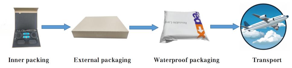
Design and packaging have a significant effect on how well an optical fiber delay line can withstand environmental variations. Even a small mechanical and thermal effect can lead to delay drift.
Our design for packaging the fiber aims at reducing the transfer of stress to the fiber as much as possible. The route and anchoring of the fiber are such that there is space for movement when the temperature changes. The stress relief areas are positioned around the splice and connectors, which are where the optical fibers are most sensitive to stress.
Material selection is equally important. Housing and internal support materials are selected to minimize strain due to temperature cycling by matching the thermal expansion behavior. This helps maintain consistent delay performance over a specified operating range.
Long-term stability is further protected by environmental sealing. Adequate protection against humidity, dust, and vibration prevents gradual degradation that would otherwise affect the delay accuracy. Application of stress-aware mechanical design combined with appropriate environmental protection enables the electric optical fiber delay line to perform in a stable way under real operating conditions, not just under laboratory conditions.
Manufacturing Control and Calibration for Consistent Performance
Tight Process Control During Assembly
For long-term stability, a great deal of reliance is placed on the repeatability of manufacture. At assembly, we are in strict control of:
- Fiber length measurement and trimming
- Splice quality and repeatability of connectors
- Assembly sequence to reduce cumulative stress
This decreases the variation from unit to unit and guarantees that each optical fiber delay line acts predictably over a period.
Calibration and Initial Stabilization
Before shipping, a delay calibration is performed on every electric optical fiber delay line under controlled conditions. It has two main purposes:
- Nominal delay accuracy verification
- Initial stabilization, allowing early-stage mechanical relaxation to take place before delivery
By addressing these effects at manufacture, the possibility of noticeable drift during early field deployment is reduced.
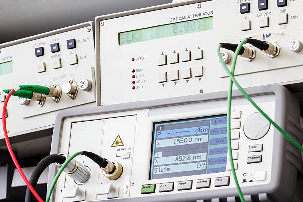
Long-Term Testing and Validation Before Delivery
Long-term stability has to be checked by test, not assumed because of design and/or material. Before shipping, individual electric-optical fiber delay lines are tested to validate the process designed to expose mechanisms of possible slow drift not measurable during shorter time scales.
The validation procedure scrutinizes the most likely causes of instability, such as:
- Delay variation after extended static operation
- Mechanical stress relaxation was introduced during assembly
- Temperature-induced delay drift over the operational range
In order to assess these effects, the delay time needs to be measured. This can be done regularly during the controlled aging and temperature cycling. These values need to be compared with the initial calibration in order to ensure that any drift within the delay time remains within the acceptable limits.
This not only enables the early stage relaxation and stabilization processes to take place during the manufacture stage and not during the field stage, but also helps ensure predictable delay performance for the optical fibers that have been delivered in terms of the delay lines.
All in All
Every phase of the product lifecycle needs to be monitored in order to achieve long-term stability of an electric optical fiber delay line. Delayed signals with stable output are obtained by selecting the right fiber, designing the mechanics with stress-awareness, controlling the manufacturing process strictly, and conducting thorough long-term tests.
We do not just look at the first specifications, but we design optical fiber delay lines to always deliver the same delay performance even in unfavorable operating conditions. Our engineers will provide you with the support of custom optical fiber delay line solutions that are designed according to the specific requirements of your system if your application needs dependable long-term delay stability both during temperature changes and over time.