Role of a Manual Variable Optical Delay Line in Fiber Optic Gyroscopes
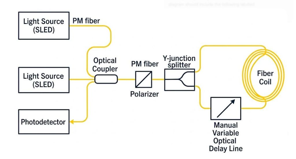
The fiber optic gyroscope (FOG) is the core component of modern inertial navigation systems and is widely used in aerospace, maritime sensing, and tactical defense platforms. The FOG operates based on the Savart effect: by splitting a single beam of light into two beams that propagate in opposite directions and placing them within an optical fiber coil to measure angular velocity. When the coil rotates, a phase difference is generated between the clockwise and counterclockwise beams.
To achieve high-precision navigation (usually measured by bias stability), the system must detect extremely small phase changes. This requires the optical path to be absolutely symmetrical. During the research and prototype development of FOG, balancing these optical paths has always been a challenging engineering problem. The solution is to integrate a manual variable optical delay line, which can provide picosecond-level precise optical path compensation, thereby eliminating system deviations before final product integration.
Why Optical Path Matching is Critical for FOG Performance?
For an ideal FOG structure, the two opposing optical beams traverse equal distances, returning to the photodetector simultaneously. In practice, however, the fabrication tolerance of fiber splicing, coupler splitting, and component assembly inevitably results in some level of OPD asymmetry.
If the two optical paths are not balanced, then the following threats arise:
- Interference Phase Noise and Drift: Fiber Optic Gyroscopes usually employ low-coherence broadband sources (like Superluminescent Light Emitting Diodes – SLEDs), which avoid such problems as Rayleigh scattering and the Kerr effect. For an unbalanced OPD larger than the coherence length of the light source, interference visibility falls dramatically, causing interference phase noise and zero-point drift.
- Environmental Sensitivity: An imbalanced system becomes very sensitive to temperature changes. Even a small temperature difference across the unequal optical path leads to nonreciprocal phase shifts (known as the Shupe Effect). The gyroscope interprets such a change as actual rotation, thereby reducing bias stability.
By making tiny adjustments in the length of one arm through an optical delay line, engineers have been able to balance out the OPD to a few submicrons, achieving optimal interference and minimizing environment-driven errors.
The Crucial Role of a Manual Variable Optical Delay Line in FOG R&D
Although automated/motorized delay lines are commonly employed in automated industrial testing applications, the use of manual variable optical delay lines remains the method of choice in FOGs research and development due to practical, technical reasons.
No Electromagnetic Interference
FOG signal-processing circuits operate based on very weak optical signals that have been translated into current values measured in microamperes. Motorized delay lines utilize stepper motors or piezoelectric drives to adjust delay line parameters. While active, these devices generate some electromagnetic interference (EMI) and heat. In the sensitive research and development laboratory environment, such EMI can interfere with the operation of FOG photodetectors or preamplifiers, thus obfuscating the actual baseline drift value. In the absence of any active electronics, a manual delay line will produce no EMI whatsoever, allowing engineers to measure the gyroscope’s true performance without external artifacts.
High-precision picosecond-level tuning
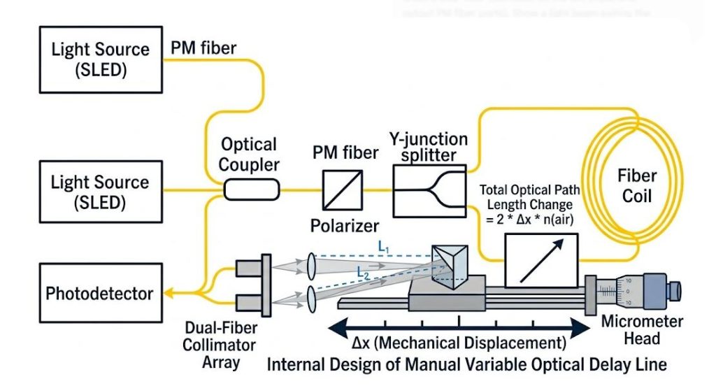
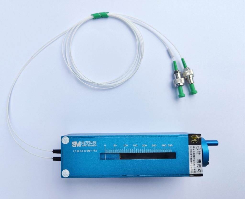
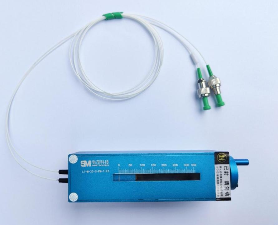
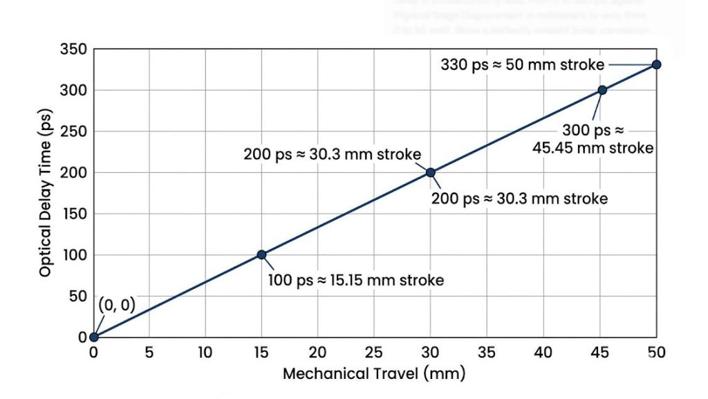
The precision required for balancing the optical path of a fiber optic grating (FOG) is far beyond what standard mechanical devices can provide. Light travels approximately 0.3 millimeters in a vacuum within one picosecond, and the speed of light in the fiber core is even slower. The manual variable optical delay line uses a precisely designed free-space optical module, driven by a micrometer with a small pitch. This physical layout allows engineers to manually adjust, with increments as small as 0.05 picoseconds or even smaller. This resolution enables ultra-fine phase tuning, thereby locking the interference pattern at its absolute peak contrast.
Cost-effectiveness and flexibility in the laboratory
The research and development workbench and university laboratories often need to modify optical devices. The electric system requires dedicated controllers, software drivers, power supplies and cables, which not only occupy the workbench space but also significantly increase the cost. The manual delay line is an independent passive optical component. It does not require an external power supply, can be used immediately after fusion, and can be easily transferred between different test platforms or prototype iterations, thereby significantly reducing the upfront development cost and accelerating the workbench testing process.
Why Polarization Maintaining (PM) Alignment is Mandatory for FOGs?
In the architecture of fiber optic gyroscope (FOG) systems, optical polarization control is of utmost importance. Standard single-mode (SM) optical fibers exhibit random, temperature-dependent birefringence, causing the polarization state of light to undergo unpredictable rotations as it propagates through the fiber coil. If two beams of light traveling in opposite directions reach the photodetector with orthogonal polarization states, they cannot interfere with each other, resulting in the complete loss of the rotation signal.
To solve this problem, the precision FOG is entirely composed of polarization-maintaining (PM) optical fibers and components. The optical delay lines integrated into the system must also be PM fibers to meet the following key requirements:
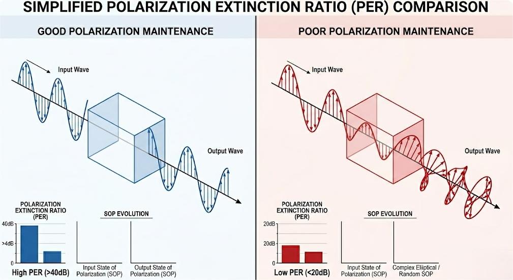
- Maintain high polarization extinction ratio (PER): The internal optical components must maintain a high polarization extinction ratio (PER) to ensure that linearly polarized light aligned with the optical fiber axis does not experience polarization crosstalk during propagation in free space.
- Minimizing non-reciprocal phase shift: Poor polarization alignment can lead to polarization coupling. This manifests as non-reciprocal phase error, which is the single largest source of unpredictable bias drift in tactical-level gyroscopes.
Therefore, a high-quality manual delay line must maintain a phase error ratio (PER) of more than 20 dB throughout the entire mechanical tuning range. By strictly maintaining the polarization state, the delay line can ensure stable interference contrast and prevent changes in ambient temperature from reducing the measurement accuracy of the gyroscope.
Selection Metrics for FOG Engineers
When evaluating the manual variable optical delay lines used for path matching in fiber optic gyroscopes (FOGs), the following four main optical and mechanical performance indicators should be given special attention:
| Metric | Target Specification Range | Engineering Impact on FOG Testing |
| Fiber Type | PM (Polarization Maintaining) Fiber | Prevents polarization cross-talk and preserves the system’s Polarization Extinction Ratio (PER). |
| Insertion Loss (IL) | < 1.0 dB (typical across full range) | Minimizes total optical link attenuation, maximizing the optical power reaching the photodetector to keep shot noise low. |
| Delay Tuning Range | 0 to 60 ps, 100 ps, or 330 ps | Determines the maximum physical fiber length mismatch (approx. 12 mm to 66 mm in fiber) that the device can successfully compensate for. |
| Locking Mechanism | Rigid mechanical screw lock | Prevents the internal mirror stage from shifting due to external acoustic vibrations or accidental bumps once the zero-OPD point is set. |
By giving priority to high phase error rate (PER), low insertion loss variation during tuning, and passive mechanical design, engineers can reliably isolate, analyze and optimize the phase performance of the fiber optic gyroscope architecture.
In fiber optic gyroscopes, perfect optical path matching is the fundamental prerequisite for minimizing phase noise and achieving ultra-high bias stability. Although automated systems offer programming convenience, in a precise research and development environment, manual adjustable optical delay lines remain indispensable diagnostic and calibration tools. They can provide sub-picosecond tuning accuracy without electromagnetic interference or thermal drift, thus providing the necessary pure test baseline for high-sensitivity optical architectures. For engineers using tactical-level fiber optic gyroscopes, choosing polarization error rate (PER) high and loss-low polarization-maintaining (PM) manual delay lines ensures polarization integrity, ultimately translating into excellent navigation accuracy and system reliability.