
The Role of Radio Frequency (RF) Amplifiers in Laser Modulation Systems
In modern photonics, to achieve high-speed laser modulation, a seamless connection needs to be established between the digital control system and the physical optical medium. For instance, advanced laser applications such as ultrafast laser material processing, multi-photon microscopy, and quantum light capture all rely on acousto-optic modulators (AOM) or electro-optic modulators (EOM) to control light.
However, optical crystals cannot be directly connected to arbitrary waveform generators (AWGs), microcontrollers, or control signals of millivolt level produced by computer systems. To move, tilt or pulse laser beams at megahertz speeds, these optical crystals require a large amount of radio frequency (RF) power. At this point, RF amplifiers become the key component of the system, as they can convert weak electronic control logic into the original physical energy required for precise laser modulation.
How RF Amplifiers Work in Laser Modulation
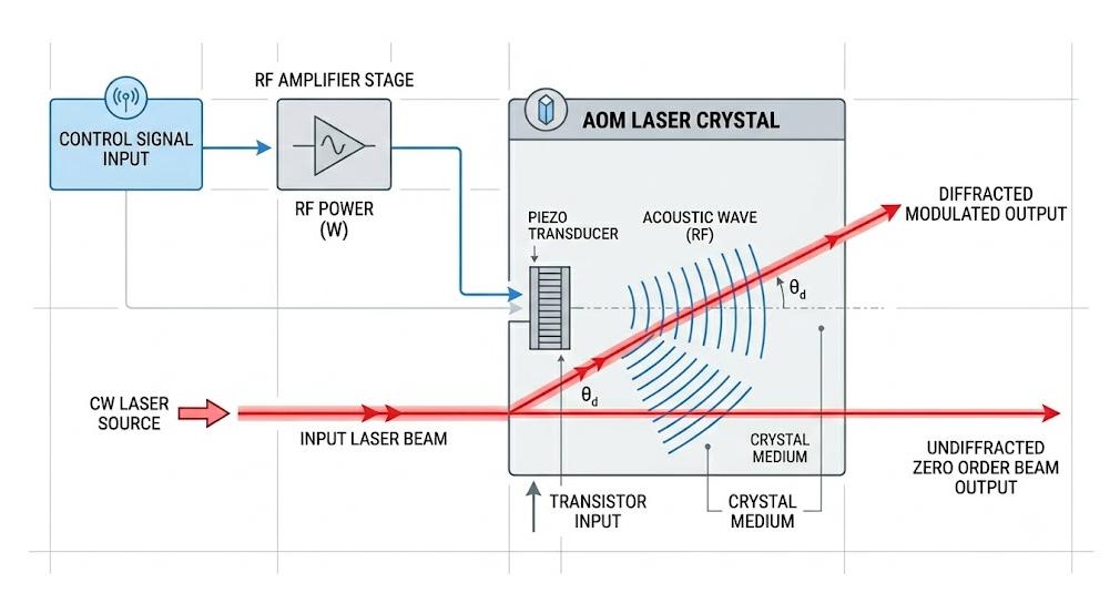
In order to fully understand the exact function of the radio frequency amplifier, it is necessary to gradually analyze the signal flow in the standard acoustic-optical modulation system. The interaction occurs within a closely synchronized electronic-optical signal chain, which converts voltage changes into optical diffraction:
Step 1: Control Signal Input
This process begins with the main system controller outputting a low-voltage control signal. This signal determines the timing and intensity of the laser modulation. It can be a fast digital TTL pulse (used for simple switching operations) or a variable analog signal (used for smooth control of the laser intensity).
Step 2: Generation of Low-Power Radio Frequency Signal
In the modulation device, the radio frequency oscillator generates a stable high-frequency carrier wave whose frequency is matched to the resonant frequency of the target crystal (for example, 80 MHz or 200 MHz). The low-voltage control signal is mixed with this carrier wave. At this point, the generated modulated radio frequency signal is very weak and is typically measured in milliwatts (mW) or milliwatt decibels (dBm).
Step 3: Amplify high-power radio frequency
This milliwatt-level signal energy is insufficient to affect the optical crystal, so it directly proceeds to the RF amplifier stage. The sole purpose of the amplifier is to increase the signal amplitude while maintaining the signal waveform unchanged, thereby raising the total output power to several watts (typically ranging from 1 watt to 5 watts, and for large industrial crystals, the power can even be higher).
Step 4: Sound wave conversion
This high-power radio frequency signal is transmitted through a shielded 50-ohm coaxial cable to the piezoelectric transducer of the acoustic-optic modulator (AOM). The transducer converts the high-power radio waves into physical sound waves, emitting high-frequency sound waves that pass directly through the internal crystal.
Step 5: Laser beam modulation
When the laser beam passes through the crystal, it will collide with the wavefront of the sound wave, and the wavefront of the sound wave acts as a temporary phase grating. The laser beam will undergo diffraction and form different angles. By changing the RF power input from the amplifier to the crystal, the brightness, time and position of the outgoing laser beam can be instantly controlled.
Key Specifications of RF Amplifiers That Determine Laser Performance
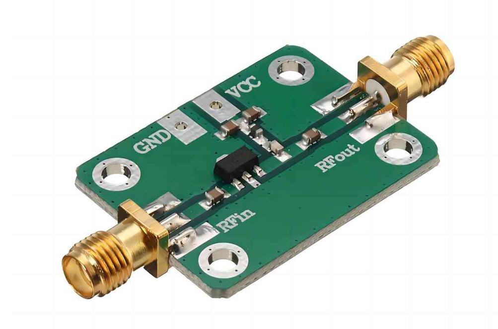
The performance of the radio frequency amplifier determines the stability, speed and accuracy of modulating the laser beam. Since the radio frequency signal generates physical acoustic waves inside the optical crystal, signal attenuation or electrical drift will immediately be converted into optical noise, power fluctuation or reduced switching speed.
To ensure compatibility and system lifespan, in addition to evaluating the pure power output, key radio frequency parameters must also be focused on.
| RF Amplifier Specification | Direct Impact on Laser System | Why It Crucially Matters |
| Bandwidth & Rise Time | Pulse Shaping & Switching Speed | Dictates how fast the laser switches from off to on. Wider bandwidth yields faster rise times, essential for high-repetition pulse picking. |
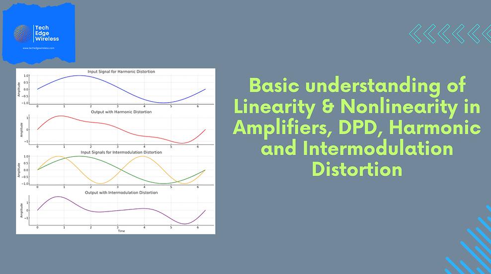
| Linearity & Compression (P1dB) | Intensity Control & Clarity | Ensures the RF output power scales linearly with control voltage. Operating past the P1dB saturation point distorts laser profiles and degrades the extinction ratio. |
| Gain Stability | Long-Term Power Consistency | Prevents the internal amplification gain from drifting as components warm up, keeping laser power steady during overnight lab runs or long production cycles. |
| Impedance Matching (50-ohm) | Return Loss & Thermal Safety | Guarantees maximum RF power transfer to the crystal. Mismatches cause Voltage Standing Wave Ratio (VSWR) reflections that can burn out output transistors. |
Broad vs. Narrowband RF Amplifiers: Which Does Your Application Need?
Selecting the appropriate RF amplifier architecture depends entirely on the characteristics of your laser application and the specific type of modulating crystal installed in the optical path layout.
Narrowband radio frequency amplifier
The narrowband driver is a highly specialized unit, and its operating frequency is a single, fixed central frequency.
The best application areas include standard laser shutters, industrial continuous wave (CW) power stabilization, laser marking, and fixed-frequency pulse selection, etc.
Since these amplifiers focus only on a narrow frequency band, they have excellent electrical efficiency, lower heat generation, and provide highly optimized and cost-effective power at their specified design frequency.
Broadband radio frequency amplifier
The broadband RF amplifier can provide a flat and stable power output over a wide frequency range, such as a continuous scan from 10 MHz to 200 MHz.
It is mainly applied in high-speed laser scanning, multi-wavelength optical systems, and devices using acoustic-optic deflectors (AOD) or acoustic-optic frequency converters (AOFS). In these configurations, the driving frequency must be actively changed in order to enable the laser beam to scan on the surface or change its color distribution.
It has excellent system versatility. A single broadband amplifier can drive various types of crystals, or easily adapt to the constantly changing experimental parameters in the research laboratory.
SMART SCI&TECH RF Solutions for Laser Precision
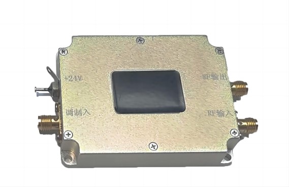
At SMART SCI&TECH, we recognize that industrial laser processing and scientific research leave no room for error regarding RF signal integrity. We engineer a premier line of high-performance RF amplifiers and integrated AOM drivers designed specifically for high-accuracy photonics.
Our advanced RF solutions deliver distinctive advantages:
- High Linearity: Optimized P1dB performance ensures predictable analog power control, essential for high-contrast imaging and micro-machining.
- Excellent Heat Dissipation: Utilizing rugged, conduction-cooled enclosures, our designs eliminate thermal drift during continuous operational cycles.
- Smart Protection: Built-in defenses against high VSWR and over-temperature conditions shield the circuitry from accidental open-circuit damage.
Whether you need a standalone broadband module or a factory-tuned driver box, SMART SCI&TECH provides the reliability your light paths depend on.
Browse our full AOM Driver & RF Amplifier Catalog or get in touch with the SMART SCI&TECH technical engineering team today to request a quote or discuss customized power, frequency, and interface configurations for your project.