
Top 3 Reasons for Signal Degradation in Optical Delay Lines and How to Prevent It
In high-precision optical networks, microwave photonics, and interferometric measurement devices, precise control of the optical phase and time is required. Motorized optical delay lines can provide picosecond or even femtosecond time resolution, making them an ideal choice for achieving this goal.
However, engineers and researchers often encounter a troublesome problem: signals gradually or suddenly weaken, typically manifested as an unexpected spike in insertion loss (IL), a decrease in return loss (RL), or severe impairment of polarization stability.
If the signal integrity of your optical system deteriorates, the underlying cause is almost always one of the following three factors. We can identify these technical flaws and learn how to prevent them, thereby maintaining picosecond-level repeatability in laboratory or industrial applications.
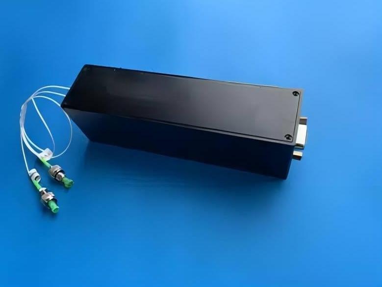
Reason 1: Connector Contamination & Misalignment
The most common cause of degradation of optical signals is very subtle: dust, oil stains, and tiny debris.
The core of an optical fiber is extremely thin – the diameter of a standard single-mode fiber (SMF) is typically only 9 micrometers. When a motorized optical delay line is designed with a free-space reflector, the light must be emitted from the fiber collimator, pass through the air to reach the moving reflector, and then be coupled back into the receiving collimator.
If particles or fingerprints deposit on the end face of the optical fiber connector or on the internal collimator lens, they will act as miniature obstacles, scattering, absorbing, or refracting the light waves, causing an immediate increase in insertion loss. Moreover, physical vibrations in the local environment or rough operations can also cause minor displacements of the internal components. Even if there is a sub-micron-level lateral or angular misalignment between the transmitting and receiving optical paths, it can lead to a sudden drop in the coupling signal power.
How to prevent?
- Implement a strict inspection process: Do not connect the fiber optic cable without checking it. Use an optical fiber endoscope to check for scratches or dirt, and use a dedicated fiber optic cleaner or a lint-free cloth dampened with 99% isopropyl alcohol to clean the end face.
- Use a robust and durable packaging design: When choosing an electric optical delay line for industrial or high-vibration environments, select the model with a fully enclosed dust-proof housing. The sturdy housing can protect the internal free space from air pollutants that may affect the alignment of the optical components, and also suppress structural micro-vibrations.
Reason 2: Mechanical Wear and Backlash in Motorized Stages
Since the motorized optical delay line relies on mechanical movement to alter the physical optical path, the quality of its internal driving system directly determines the long-term performance of its optical properties.
To change the delay time, the stepper motor or servo motor drives the translation stage to move along the linear guide rail through the lead screw or ball screw. In platforms that are of lower quality or poorly maintained, continuous operation will cause friction, which leads to physical wear on the mechanical threads. This wear introduces backlash – the small gap or “play” existing in the mechanical connection when the motor reverses.
Mechanical wear and recoil will reduce signal quality from two aspects.
- Firstly, they will introduce structural inclination or oscillation during the platform’s movement, causing the reflecting mirror to deviate from the optimal optical axis, thereby resulting in fluctuations in local insertion loss.
- Secondly, they will disrupt the repeatability of the delay of the system. The motor may report having returned to exactly the same position, but due to mechanical clearance, the actual physical position will have a slight deviation, thereby generating phase errors and time jitter.
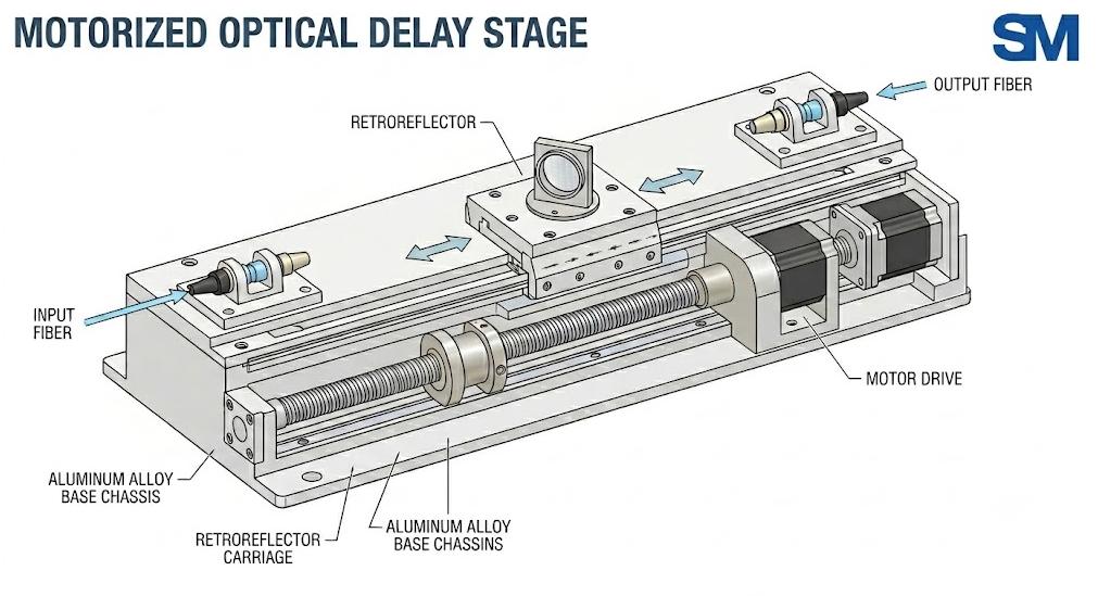
How to Prevent It?
- First, choose manufacturers that adopt non-rebound structure configurations, such as pre-tightened ball screws or direct-drive linear motors.
- Secondly, ensure that the electric platform is equipped with high-resolution linear encoders to achieve closed-loop feedback. Closed-loop control continuously monitors the actual physical position of the platform, automatically compensates for mechanical errors, and ensures the sub-picosecond level repeatability of the cycle.
Reason 3: Thermal Drifts & Polarization Instability
Optical components themselves are highly sensitive to temperature changes, and the optical delay line is no exception.
The principle is as follows:
Temperature fluctuations in laboratories or industrial facilities can affect optical fibers and mechanical enclosures.
- In optical fibers, temperature changes alter the refractive index and cause slight physical expansion or contraction, thereby directly altering the baseline delay.
- In terms of mechanics, standard aluminum or steel platforms expand as the temperature rises, which subtly alters the distance between optical components and ultimately affects alignment.
For systems using polarization-maintaining (PM) optical fiber delay lines, temperature variations pose a greater threat: polarization cross-talk. If the stressed components within the PM optical fiber are subjected to thermal stress or mechanical compression caused by the expansion of the housing, the birefringence of the fiber will change. This will reduce the polarization extinction ratio (PER), and when the signal interferes with other optical paths downstream, it will lead to power fluctuations and phase noise.
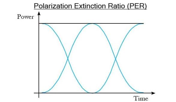
Here are the prevention methods:
- Implement thermal compensation design: Choose a light delay line manufactured with advanced materials (such as steel components with low thermal expansion coefficient), or opt for a design with built-in passive thermal compensation.
- Perform thermal isolation for the device: Keep the optical delay line away from air conditioning vents, cooling fans, or high-power equipment that generates local heat. In critical applications, deploying the device in a temperature-controlled enclosure or an optical isolation box can significantly improve long-term phase stability.
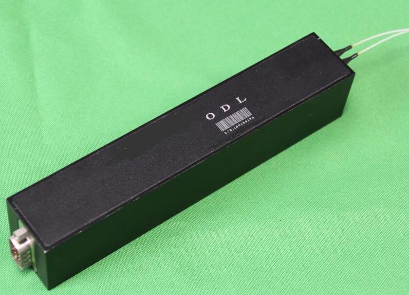
Summary of Signal Degradation and Prevention
| Issue / Symptom | Root Cause | Preventive Action |
| High Insertion Loss (IL) & Low Return Loss (RL) | Dust, debris, or micro-misalignment of optics | Clean connectors before mating; select dust-proof, enclosed designs. |
| Fluctuating Signal Power & Poor Repeatability | Mechanical wear, friction, and stage backlash | Upgrade to backlash-free drive mechanics with closed-loop linear encoders. |
| Phase Noise & Degradation of PER | Environmental temperature swings & thermal stress | Deploy thermal compensation hardware; isolate the device from heat sources. |
The signal attenuation in the motorized optical delay line is rarely a random failure; it is usually a controllable engineering challenge. By establishing strict fiber cleaning procedures, avoiding extreme temperature changes, and – most importantly – investing in hardware that can withstand mechanical and thermal stresses, you can fully ensure the integrity of the signal.