Lab-Grade vs. Industrial-Grade: Why Environmental Stability is Crucial for Your Optical Delay Line?
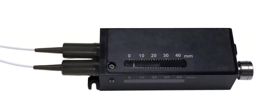
The Optical Delay Line (ODL) is a highly precise instrument when used under laboratory-controlled conditions. Nevertheless, if this device is to be used for radar calibration, fiber sensing, or medical imaging, it will have to move out of the clean room into the “field” environment. In this context, poor performance is not a matter of optical design but rather of environmental stress.
To achieve high-speed and low-loss signal control, engineers must look beyond basic step-accuracy and prioritize environmental stability.
The Real Impact of Environmental Challenges
Thermal Drift and Preservation of Length
Temperature is the main problem for optical accuracy. Almost all optical fibers possess some thermal-optical coefficient affecting the change in the refractive index as well as physical length due to temperature variation. In an outdoor telecommunication base station or on the laser production line, a temperature difference of just 10°C might result in picoseconds delay drift.
Mechanical Vibration and Coupling Efficiency
Vibration at low frequencies is inevitable during sensing applications (for instance, in coal mines or bridges). In space-light delay lines and optical interfacing between two optical fibers, mechanical vibrations cause micro-displacements, leading to Power Variations and Insertion Loss (IL) pulses, which can desynchronize sensitive interferometric systems
Humidity and Lifespan of Components
Humid environments allow moisture to penetrate, causing corrosion of the optical coatings and affecting the electronic components of the Electric Optical Fiber Delay Line. This will result in corrosion to the motor tracks and possible electronic failure in the long run.
Technical Deep Dive: The CQ-SMART 3rd Generation Advantage
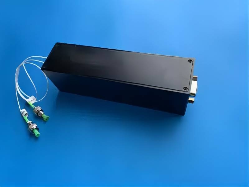
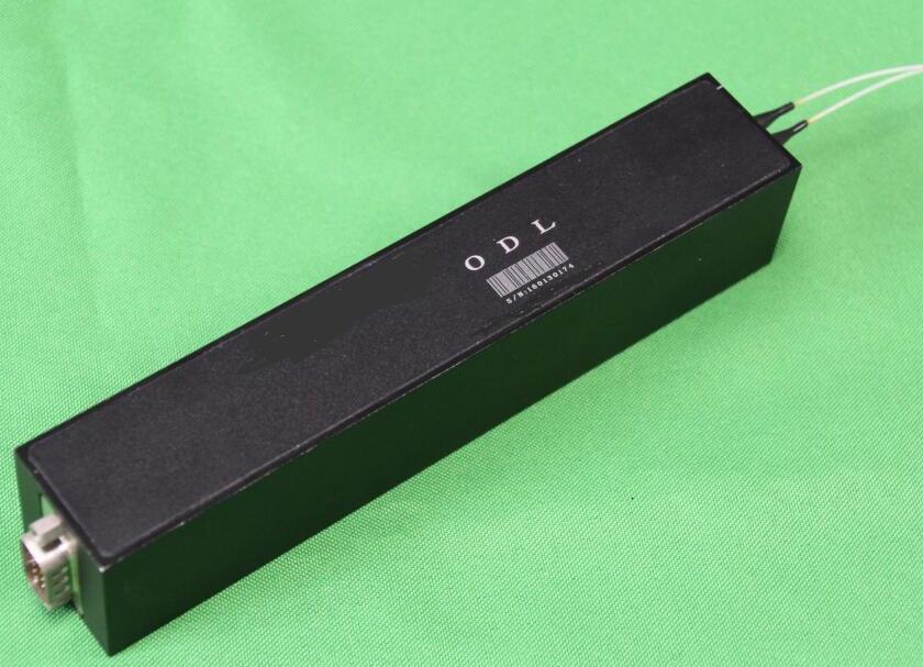
Where conventional delay lines usually suffer mechanical hysteresis and thermal instability, SMART SCI&TECH has designed its 3rd Generation Optical Delay Line (ODL) system precisely for overcoming this hurdle. The 3rd generation ODL system marks an important step in terms of these aspects. Indeed, this generation represents a significant leap in structural integrity and signal consistency, moving beyond simple delay functions to true environmental resilience.
Enhanced Mechanized Stability and Intact Signal Pathway
The key feature of our 3rd Generation superiority lies in the development of our proprietary reinforced mechanical delay mechanism that is resilient enough to endure the tough conditions on-site. The inherent flaw of the conventional “floating” internal optical components is that they can easily be affected by outside forces that induce microscopic displacements and consequently cause destructive signal jitter. This problem has been overcome through:
- Vibration-Resistant Guidance System: By using precise rail technology that will dampen low-frequency industrial vibrations and make sure that the physical optical path remains intact.
- Minimized Lever Effect: Through careful selection of the optimal internal optical arm center of gravity, any misalignments due to non-horizontally mounting of the device are prevented, which would occur, for example, in radar systems.
- Thermal-Mechanical Compensation: By selecting materials with a low thermal expansion coefficient, to guarantee that a 10°C difference will not add up to picoseconds of additional drift.
This structural overhaul ensures that whether the ODL is integrated into a high-vibration turbine monitoring system or a sensitive interferometric array, the signal remains phase-stable.
Durable Construction for High-Cycling Durability
In addition to just precision, industries also look for durability. While most delay line products in laboratories can work for a few changes, today’s automatic tests and OCT devices require thousands of cycles per day without wearing out.
- Highly Durable Drive Tracks: Electrically-driven products come with high-torque motors and special coating on their tracks for millions of cycles with sub-micron precision.
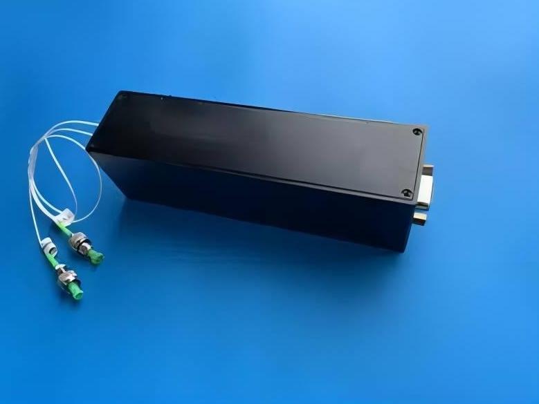
- Protected Optical Pathways: To resist the “field” environment, our 3rd Gen units ensure their pathways’ seal for protection against dust and other factors that might damage optical coatings.
- Speed with Low IL: Optimized for the wavelengths between 532nm and 2000nm, it provides excellent Low Insertion Loss (IL) despite moving at high speeds.
In conclusion, CQ-SMART Optical Delay Line is more than a mere optical device; it is reliability insurance that you can set once and forget about. The precision of quantum-grade devices and the strength necessary for 24/7 operations have been merged to provide you with accuracy under any environmental conditions.
Practical Application Scenarios

In modern radar testing, simulating long-distance target echoes requires nanosecond-level timing accuracy. Outside laboratory environments, temperature fluctuations often cause “delay drift.” CQ-SMART’s 3rd Gen Electric ODLs provide high-speed, programmable calibration that remains stable despite ambient thermal changes, ensuring that range-finding algorithms remain accurate in the field.
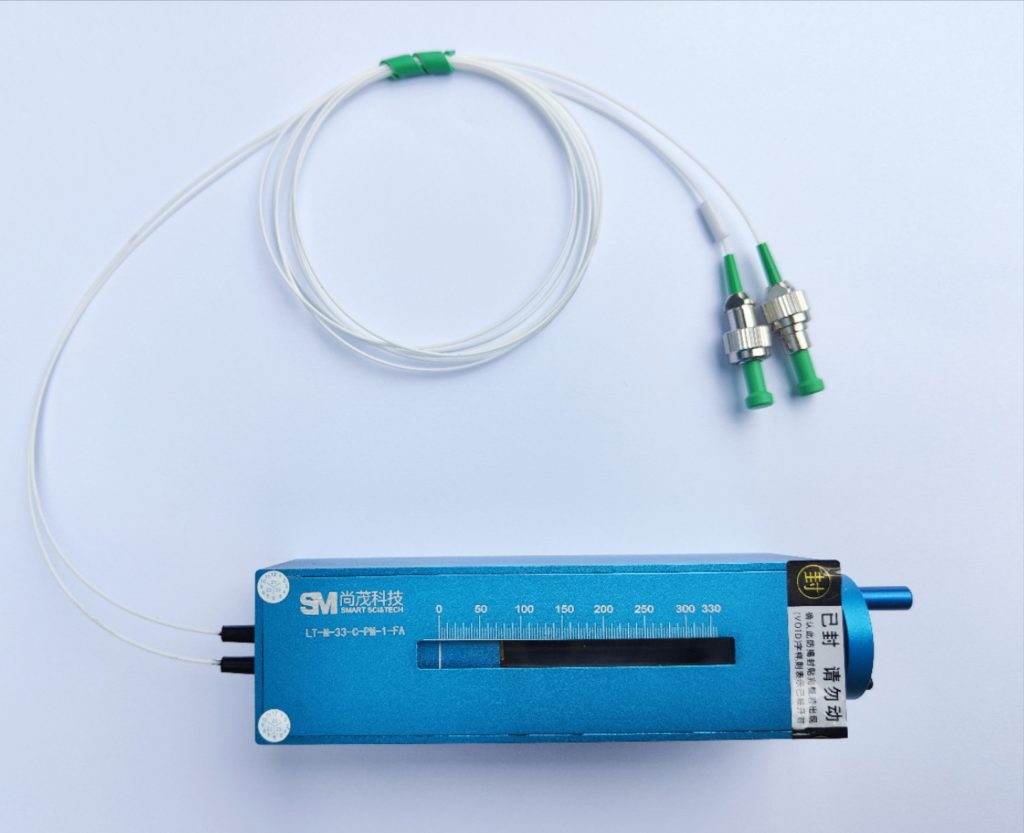
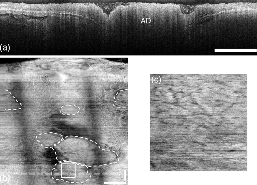
Resolution along the depth axis in an OCT image is determined by the accuracy with which the optical path of the reference arm is calibrated. The slightest mechanical vibration during the scan causes noise in the image. Our manual and electric ODLs are constructed using a specially designed lock-in system to eliminate micron-level shifts, delivering the repeatable, high-resolution cross-sectional scans required for clinical diagnostics.
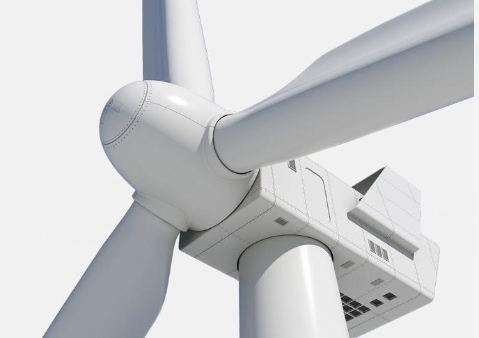
For applications such as wind turbines or bridges, the sensors are expected to be immune to prolonged low-frequency vibration. Ordinary delay lines may experience coupling loss in such cases. Our robust 3rd Gen design ensures that the phase-matching remains intact, preventing signal dropout in high-vibration industrial zones.
The Industrial Buyer’s Checklist
For the continued resilience of your system out in the real world, procurement shouldn’t stop at simple delay requirements. In assessing your optical delay line for B2B applications, follow this checklist:
- Hysteresis: Does your device accurately revert to the same picosecond point after 10,000+ cycles? High hysteresis is imperative for automated testing.
- Thermal-Optical Stability: Ask for information regarding the delay drift with respect to changes in temperature. Consider devices that utilize low thermal expansion materials.]
- Housing Integrity: During field operation, verify the level of sealing. Is the optical pathway within the device shielded from particulates, dampness, or moisture contamination?
- Vibration Resistance: Ask whether the guidance system is strengthened to guard against signal jitter due to continuous vibration stress.
- Wavelength Compatibility: Verify that the manufacturer will tune the coating and alignment according to your wavelength range (such as 780nm, 1064nm, or 1550nm).
To Conclude
At SMART SCI&TECH, we understand that precision in a laboratory is the baseline; precision in the “field” is our specialty. Our commitment to 3rd generation Optical Delay Line technology is a commitment to your system’s long-term uptime and signal integrity.
Explore our Optical Delay Line Products or contact our technical team at [email protected] for a custom quote!