Why Your AOM Extinction Ratio Underperforms? Five Overlooked Installation Details
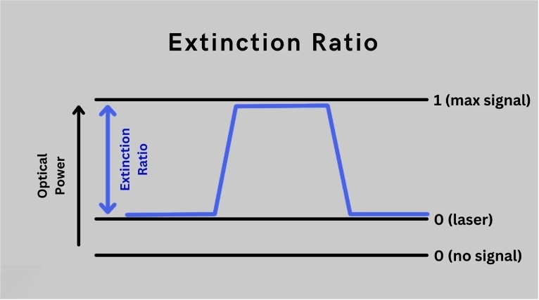
The extinction ratio of an Acousto-Optic Modulator is usually a limiting factor in precision laser systems. Although a manufacturer’s specification for an aom extinction ratio of 40dB or 50dB is possible, achieving this on an actual optical bench is notoriously difficult.
If your “OFF” state is leaking too much power or your pulse contrast is degraded, it’s not usually a problem with a defective crystal, but a slight misalignment in physical or electronic integration. To improve your AOM modulator, you need to consider these five overlooked installation factors.
Precise Bragg Angle and Beam Centering
The basic principle of efficiency in acoustic optical modulators is based on Bragg’s principle. If the laser beam is not incident on the wavefront of the acoustic wave at the Bragg angle, then there is a decrease in diffraction efficiency and a corresponding increase in static leakage in the first-order path.
- The Error: Most technicians adjust for maximum brightness in the “ON” state and then stop there. However, maximum diffraction efficiency is not necessarily equal to maximum extinction ratio.
- The Fix: Utilize a high-sensitivity power meter to measure the leakage in the “OFF” state. Make adjustments in micro-radian increments.
- Centering Matters: The beam needs to go through the center of the acoustic field. If your beam is close to the transducer or on the far edge of the crystal, you will get acoustic field non-uniformity, which will scatter light and destroy the ER.
Polarization Alignment and PER Matching
Most high-performance acousto-optic modulators are polarization-sensitive. Whether using Tellurium Dioxide (TeO2) or Crystalline Quartz, the orientation is optimized for linear (vertical/horizontal) or circular polarization.
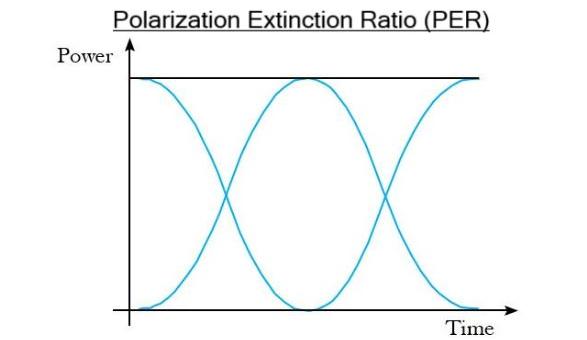
- Polarization Extinction Ratio (PER): If your laser input has a low Polarization Extinction Ratio (PER), i.e., less than 20dB, the “unwanted” polarization component will pass through the crystal unmodulated. This unwanted component will show up as a constant level of “leakage” which no amount of RF optimization can eliminate.
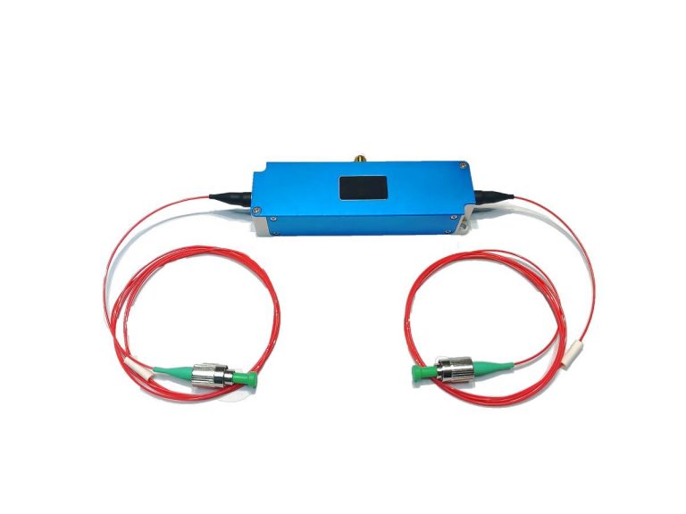
- The Detail: Make sure your half-wave plate is high quality and properly oriented. For the case of the fiber-coupled AOM modulators, the stress on the PM fiber can rotate the polarization axis. Always re-check the polarization state at the point of entry into the AOM housing.
RF Driver Signal Leakage and Noise Floor
The aom extinction ratio is also fundamentally limited by the “purity” of the RF “OFF” state. If the RF driver continues to provide even a few microwatts of power when the state should be zero, the crystal continues to diffract light.
- RF Isolation: Many low-cost RF drivers also lack good isolation between the modulation input signal and the RF output signal. If the internal shielding within the RF driver is not well designed, the RF carrier signal leaks through even when the modulation signal is at zero volts.
- EMI and Grounding: In an industrial environment, EMI from nearby high-voltage power supplies can induce a low-level signal in your RF cables.
- The Test: The best way to determine whether the issue is with the driver is to remove the SMA cable from the AOM modulator. If the extinction ratio improves immediately, then your RF driver is the source of the leakage/noise floor issue.
Beam Waist vs. Acoustic Velocity
The interaction between the laser beam diameter and the acoustic wave velocity determines the contrast ratio.
| Setup Choice | Benefit | Risk to Extinction Ratio |
| Tight Focus (Small Waist) | Faster rise time / switching speed. | High divergence may exceed the AOM acceptance angle, causing “halo” leakage. |
| Collimated (Large Waist) | High diffraction efficiency across the beam. | Slower response time; potential for non-uniform modulation depth. |
Pro Tip: For TeO2 slow shear aom modulators, the acoustic velocity is about 617 meters/s. Your beam divergence must be strictly less than the acoustic beam divergence to maintain a clean ER.
Thermal Gradients and Mounting Tension
The acousto optic modulator will produce heat during RF operation. If not controlled, thermal effects will alter your alignment.
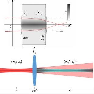
- Thermal Lensing: If the refractive index of the crystal changes because of improper heat sinking, then your ER might drop after 10 minutes of operation. This means that there is a thermal gradient problem.
- Mounting Stress: If the clamps used to hold the housing are over-tightened, then “stress birefringence” occurs. This physically rotates the polarization of your laser inside the crystal, resulting in a floor that cannot be aligned.
- Mounting Best Practice: A flat, high-conductivity copper or aluminum cold plate should be used. Moderate, even pressure should be applied to the housing.
Comparison of Factors Impacting Extinction Ratio
If your acousto-optic modulator is not functioning up to its rated AOM Extinction Ratio, the following diagnostic logic can be employed to determine the point of failure:
Static Leakage: If the light is still leaking in the “OFF” state even with the SMA cable disconnected, the point of failure is purely optical.
Dynamic Drift: If the AOM modulator is functioning well to start with, but the performance degrades after 10 minutes, the point of failure is thermal, which is related to heat sinking.
Electronic Ghosting: If the leakage is present even when the driver is connected but “quiet,” the point of failure is related to RF leakage and port isolation.
| Symptom | Primary Root Cause | Corrective Action |
| Consistent Low ER | Polarization axis mismatch | Rotate HWP or re-align PM fiber axis. |
| Zero-order Leakage | Sub-optimal Bragg Angle | Fine-tune rotation stage for “OFF” state null. |
| ER Drifts Over Time | Thermal gradient in crystal | Improve thermal contact with copper baseplate. |
| RF “OFF” Leakage | High RF driver noise floor | Replace SMA cable or check driver isolation. |
| Distorted First-order | Beam clipping or centering | Re-center beam through the clear aperture. |
| Scattered “Halo” | Excessive beam divergence | Increase beam waist to match acoustic acceptance. |
Pro Tip: Always verify the acoustic optical modulator input PER first. If your source laser PER is below 25dB, no amount of mechanical alignment will recover the extinction ratio.
About SMART SCI&TECH
At SMART SCI&TECH, we specialize in the design and manufacturing of precision acousto-optic modulators for quantum research, industrial marking, and fiber sensing. Our engineers are available to offer in-depth technical support for your specific application to help you achieve the highest possible aom extinction ratio in your system.
Need a technical consult? Send us your system parameters!