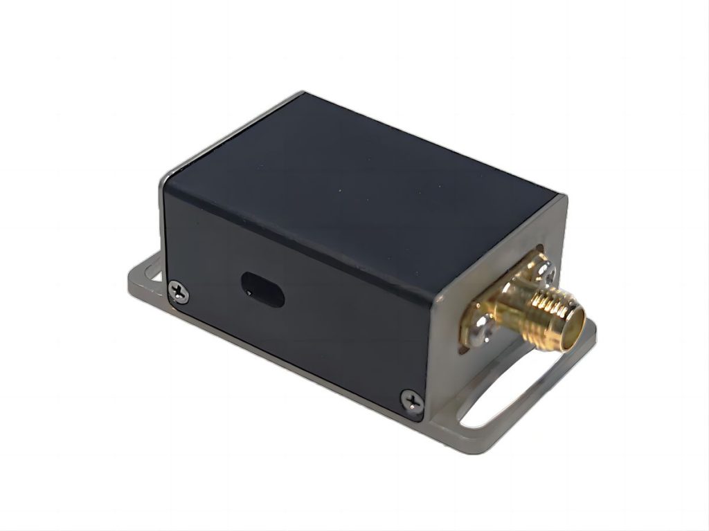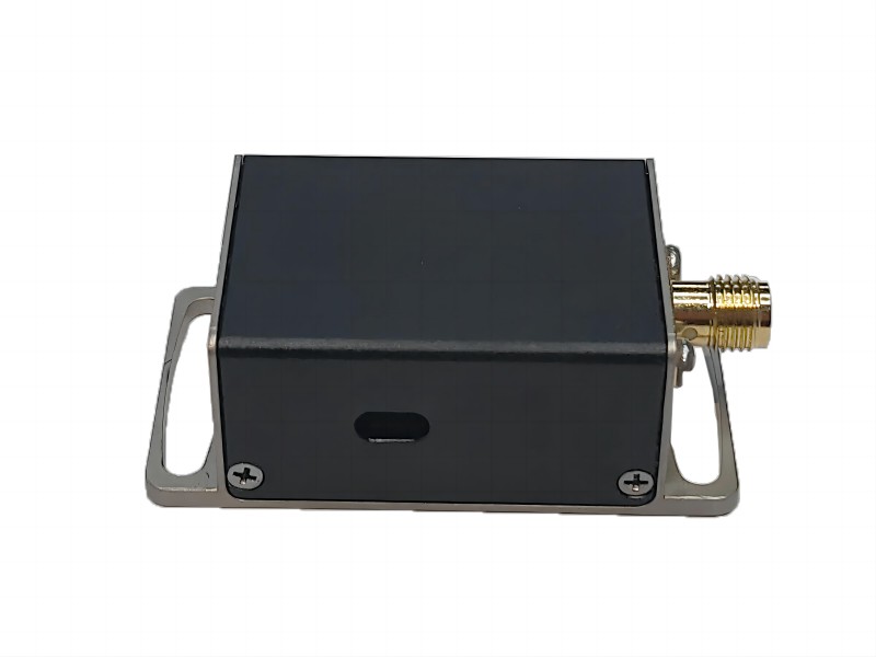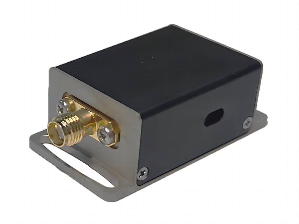
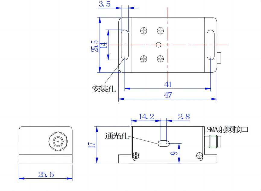
397nm Space AOM Series
Acousto optic modulator is a kind of photoelectric product that uses the principle of acousto-optic interaction to modulate the laser intensity and shift the frequency. Its rate control and modulated light intensity far exceed the mechanical shutter. The wavelength range is from the ultraviolet region to the mid-infrared region. The use of the recommended supporting driver can achieve the best performance and more application options.
Characteristics of 397nm Space AOM Series
- Fast modulation speed
- High diffraction efficiency
- High-temperature stability and reliability
- Small size
Applications of 397nm Space AOM Series
- Lidar
- Material processing
- Laser Doppler system
- Image processing
- Cold atomic physics
Ordering Information of 397nm Space AOM Series
This indicator is a typical optical wavelength indicator, and other wavelengths and frequencies can be selected.
| Parameter | Unit | SGT130-397-1QP1-HP | SGT100-397-1TA | SGT200-397-0.5TA | SGT300-397-0.2TA |
| Wavelength | nm | 397 (Typical value) | |||
| Polarization state of input light | – | linear polarization(⊥) | arbitrarily | ||
| Center frequency | MHz | 130 | 100 | 200 | 300 |
| Diffraction efficiency | % | ≥80 | ≥85 | ≥85 | ≥85 |
| Frequency shift bandwidth | MHz | 30 | 20 | 50 | 60 |
| Optical aperture | mm | 1 | 1 | 0.5 | 0.2 |
| Diffraction light separation angle | mrad | 9 | 17 | 19 | 28.4 |
| Drive power | W | ≤4 | ≤1.5 | ||
| Rise time of light pulse | ns/mm | 120 | 160 | ||
| Damage threshold | W/mm2 | 10 | 0.1 | ||
| Static transmissivity | % | 95 | 90 | ||
| Extinction ratio | – | >1000:1 | |||
| RF connector | – | SMA | |||
| Input impedance | Ω | 50 | |||
| VSWR | – | <1.3:1 | |||
| Cooling mode | – | Conduction cooling | |||
| Material Science | – | quartz | tellurium oxide | ||
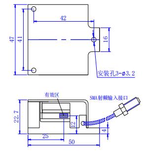
| Package | – | QP1 | TA | ||
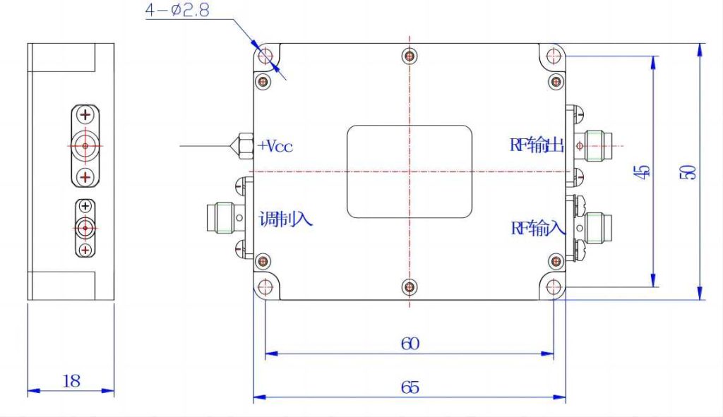
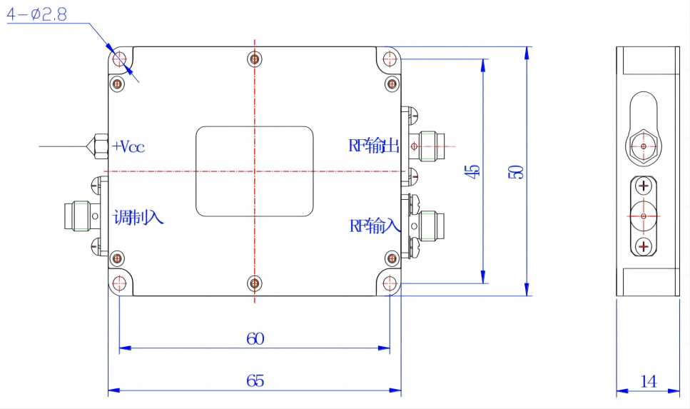
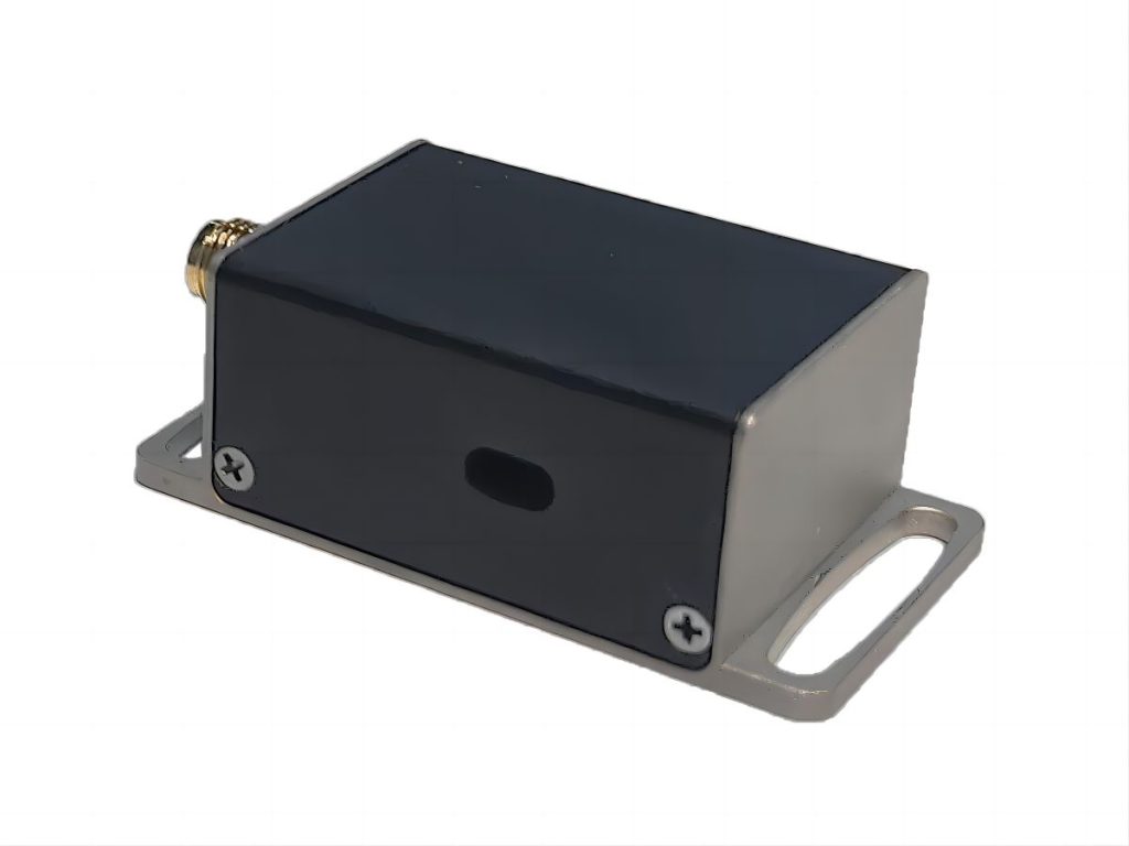
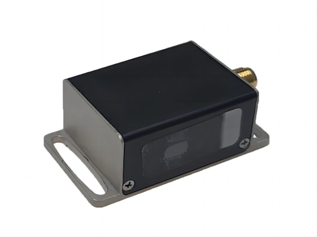
Low-power N-type Acousto Optic Driver for 397nm Space AOM Series
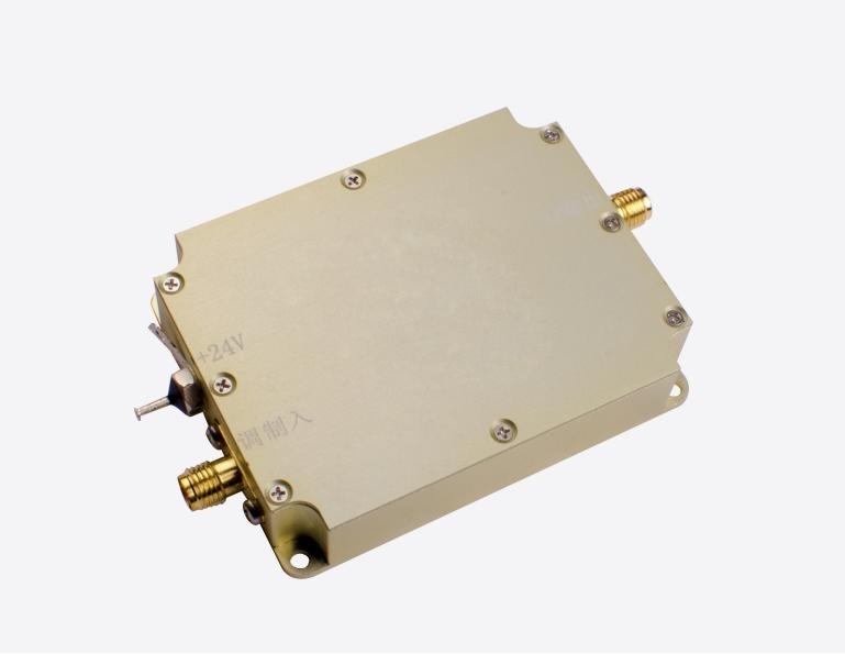
A typical RF driver comprises an RF oscillator, a modulation circuit, and a power amplifier. It produces RF signals utilized for generating sound waves within the crystals of the AO device. The modulation and strength of the RF signal dictate the extent of modulation, deflection, or tuning of the beam. This acousto-optic driver enables both digital and analog modulation of the beam, along with frequency shifting capabilities. With efficient heat dissipation and reliable performance, the driver ensures stability when paired with compatible acousto-optic devices.
| Supporting Drive | Model (SGXXXX-33-N-ab): For the frequency shift function, designate “Y,” and for the modulation function, designate “T.” In the code, “XXX” represents the operating frequency, where “33” corresponds to RF output power. The “N” signifies the package type. Regarding power supply voltage, use “1” for 24V and “2” for 12V. Lastly, for modulation, use “D” for digital TTL modulation and “A” for analog modulation. | ||||||
| SGT100-33-N2-1D SGT100-33-N2-1A1 SGT100-33-N2-1A5 | SGT180-33-N2-1D SGT180-33-N2-1A1 SGT180-33-N2-1A5 | SGT200-33-N-1D SGT200-33-N-1A1 SGT200-33-N-1A5 | SGT300-33-N2-1D SGT300-33-N2-1A1 SGT300-33-N2-1A5 | ||||
Performance of Low-power N-type Acousto Optic Driver on Space AOM
- Small size
- Fast response time
- Low power consumption
- High-temperature stability and reliability
| Item | Unit | Specifications of the modulation input interface | |||
| Specifications of modulation input interface | |||||
| Modulated signal input | – | Digital modulation (high level 3.3-5V; low level 0-0.2V@1k Ω) Analog modulation (A1: 0-1V@50 Ω) Analog modulation (A5: 0-5V@1k Ω) | |||
| Interface | – | SMA | |||
| RF output interface specification | |||||
| Output signal frequency | MHz | 130 | 180 | 200 | 300 |
| Frequency stability | ppm | 100 ( 1 Special) | |||
| Rise and fall time | ns | <25 | <25 | <10 | <7 |
| Output signal power | W | <2 | |||
| Switching ratio | dB | ≥60 | |||
| Harmonic suppression ratio | dBc | >25 | |||
| Signal output standing wave ratio | – | ≤1.3 | |||
| Interface | – | SMA | |||
| Complete machine specification | |||||
| Maximum power consumption | W | 10 | |||
| Working voltage | Vdc | 24±1V(Optional 12±0.5) | |||
| Power interface | Through core capacitance (core wire is connected to positive, solder lug is connected to negative) | ||||
| Package | – | N/N2 | |||