9 Key Performance Indicators of RF Amplifiers
In modern communication, radar, test instruments, and satellite systems, the radio frequency Amplifier (RF Amplifier) is an indispensable key component. Whether it is low-noise amplification (LNA) at the signal receiving end or power amplification (PA) at the transmitting end, the performance indicators of the amplifier directly affect the overall performance of the system.
Understanding the main parameters of RF amplifiers not only helps engineers make selections and matches during the design stage, but also assists purchasing personnel in judging the advantages and disadvantages of different models of amplifiers.
Basic Concepts of RF Amplifiers
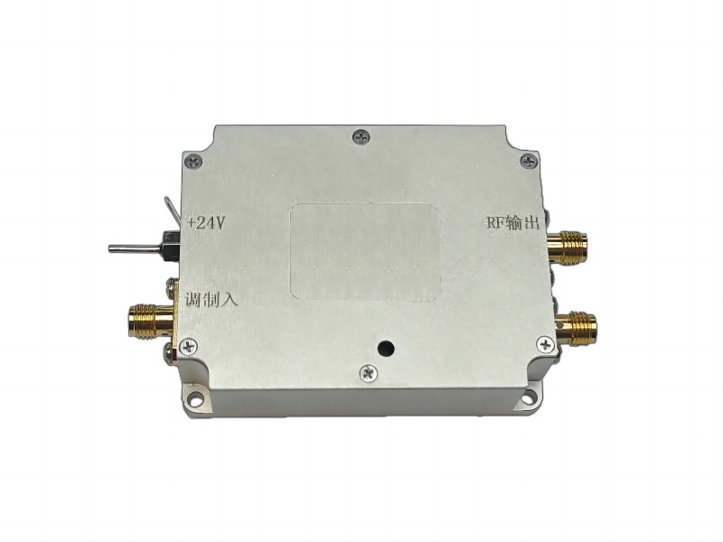
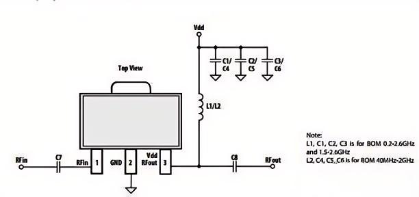
The radio frequency amplifier (RF PA) is an important component of various wireless transmitters. In the pre-stage circuit of the transmitter, the RF signal power generated by the modulation oscillation circuit is very small. It needs to go through a series of amplifications (buffer stage, intermediate amplification stage, and final power amplification stage) to obtain sufficient RF power before it can be fed to the antenna for radiation. To obtain a sufficiently large RF output power, an RF power amplifier must be used. After the modulator generates the radio frequency signal, the modulated radio frequency signal is amplified to sufficient power by the RF PA, passes through the matching network, and is then transmitted by the antenna.
The function of an amplifier is to amplify the input content and output it. The content of input and output, which we call “signals”, is often represented as voltage or power. For a “system” like an amplifier, its “contribution” is to elevate what it “absorbs” to a certain level and then “output” it to the outside world. If the amplifier can have good performance, then it can contribute more, which reflects its own “value”. If the amplifier has certain problems, then after it starts working or has been in operation for a period of time, it will not only fail to provide any “contribution”, but may also experience some unexpected “oscillations”. Such “oscillations” are disastrous for both the outside world and the amplifier itself.
Output Power and 1dB Compression Point (P1dB)
When the input power exceeds a certain value, the gain of the transistor begins to decline, causing the output power to saturate and resulting in nonlinear distortion. The 1dB compression point indicates the point where the output power of the amplifier deviates from the constant or is 1dB lower than the gain of other small signals. P1dB is an important indicator for measuring the linear output capability of an amplifier. The higher it is, the better the amplifier can maintain good linearity under high power input and avoid signal distortion.
Gain
The ratio of the output power to the input power of an amplifier, measured in decibels (dB), is the working gain, which is the main indicator for measuring the amplification capability of an amplifier. Gain flatness refers to the range within which the amplifier’s gain varies across the entire operating frequency band at a certain temperature. It determines whether the amplifier can provide uniform amplification effects throughout the entire operating frequency band.
Operating Frequency Range
It generally refers to the linear operating frequency range of the amplifier, that is, within which frequency range the amplifier can operate normally. It is usually expressed in the lowest and highest frequencies, for example, “500 MHz – 6 GHz”. Different types of RF amplifiers are designed for different frequency bands. If the frequency exceeds its operating range, both the gain and linearity will decline significantly.
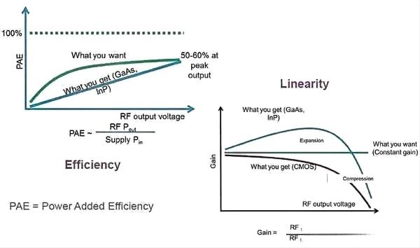
Efficiency
The efficiency of the amplifier is of great significance to the overall efficiency of the system. It is the ratio of the high-frequency output power of the amplifier to the DC power provided to the transistors. High-efficiency amplifiers can consume less electrical energy and generate less heat while outputting the same power. This is crucial for high-power transmitters, portable devices and battery-powered systems.
Intermodulation Distortion (IMD)
It refers to the mixed component generated by two or more input signals with different frequencies passing through a power amplifier, mainly due to the nonlinear characteristics of the amplifier. IMD can cause signal crosstalk, interfere with adjacent channels and reduce the signal quality of the system.
Third-order Intermodulation Cut-off Point (IP3)
It refers to the fact that when the output power is constant, the greater the output power at the third-order intermodulation cut-off point of the amplifier, the better the linearity of the amplifier. The higher the IP3, the better the linearity of the amplifier and the stronger its anti-distortion ability.
Harmonic Distortion
In high-power amplifier systems, it is necessary to reduce high-order harmonics to a certain level through filters. Harmonic distortion can contaminate the spectrum and interfere with other systems.
Dynamic Range
It refers to the difference between the amplifier’s minimum detectable signal and the maximum input power in the linear operating region. The larger the dynamic range, the wider the signal strength range the amplifier can operate without distortion. For wireless receivers and measuring devices, this is directly related to the system’s sensitivity and anti-interference capability.
Input-output Standing Wave Ratio (VSWR)
It shows the matching degree between the RF amplifier and the overall system, which has a significant impact on the gain fluctuation and group delay of the system. Good impedance matching can maximize signal transmission efficiency and reduce reflection and power loss. If the VSWR is too high, it will cause signal reflection, gain fluctuation and even amplifier damage.
How to Choose An Amplifier Based On The Application Scenario
After understanding the indicators themselves, how to select RF amplifiers in practical applications? The key lies in identifying the principal contradiction based on the application scenarios.
Scene One: Front end of the receiver – Low-noise amplifier
- Primary indicators: Low noise figure, high gain. The goal is to amplify weak signals as losslessly as possible without introducing additional noise.
- Secondary guarantees: Sufficient linearity to withstand strong out-of-band interference, as well as absolute stability.
Scene Two: Transmitter final stage – Power amplifier
- Primary indicators: High output power, high efficiency, and high linearity. This is a classic “Iron triangle” trade-off.
- For constant envelope signals such as GSM, a certain degree of linearity can be sacrificed to pursue extremely high efficiency.
- For high-PAR signals such as 5G and LTE: high linearity must be prioritized to avoid spectrum regeneration and adjacent channel interference, at which point efficiency will correspondingly decrease.
- Secondary guarantee: Good VSWR to protect the power amplifier tubes.
Scene Three: General-purpose driver/Intermediate amplifier
- Primary indicators: High gain, wide bandwidth, and good linearity. Its main task is to provide stable gain and drive the subsequent circuit.
- Secondary guarantees: Moderate noise figure and efficiency.
Summary
The nine indicators of a radio frequency amplifier form an interrelated and mutually restrictive whole. The gain and noise figure determine its ability to handle small signals. P1dB and IP3 define the boundaries for handling large signals without distortion. Efficiency and VSWR are related to the power consumption and reliability of the system. Stability and bandwidth are the foundation and stage for its normal operation.
Want to explore more RF technology resources and solutions? Visit SMART SCI&TECH now for complete product specifications, pricing, and professional support.