AOM Driver for Semiconductor Wafer Inspection: Maximizing Precision and Reliability
In terms of wafer inspection, the laser will not function properly unless it is appropriately modulated. If there are problems with frequency modulation and/or the transition pulses in the AOM controller, then your inspection equipment can give you some erroneous readings of defects or lose resolution. This isn’t just about technology, but about economics too, for semiconductor manufacturers.
This article covers the requirements for designing hardware for RF drivers for metrology applications.
How the AOM Driver Enhances Inspection Systems in Three Dimensions
Controlling Beam Jitter via Frequency Precision
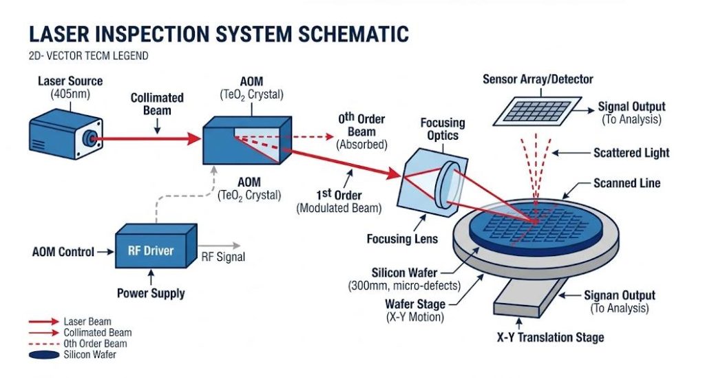
In the scanning metrology system, the acoustic-optic modulator (AOM) driver is not merely a power supply but also a positioning tool. Due to the locking of the diffraction angle to the radio frequency frequency, even a slight frequency drift (usually caused by the heating of internal components) will cause the laser spot to “wander” on the wafer.
For process nodes of 7nm and below, this jitter is unacceptable. We have found that using standard oscillators usually leads to pixel offset errors, thereby disrupting the spatial integrity of the scan. To solve this problem at the hardware level, we integrated a high-stability OCXO (constant temperature crystal oscillator). By keeping the frequency within a tolerance range of ±0.5 ppm, the driver ensures that the primary beam is always located exactly at the center of the sensor. This does not require complex software image correction, saving the system’s processing capacity and enabling it to be used for actual defect analysis.
Why the Extinction Ratio Defines Your Noise Floor
Engineers sometimes overlook the “shutdown” performance of the drive, but this is particularly important in dark-field detection. If the isolation of the drive is poor, residual radio frequency power will leak into the crystal. This will create a “weak” laser background, masking the weak signals scattered by 10nm or 20nm particles.
We focus on the isolation level of the output stage to increase the extinction ratio to above 40dB. The goal is simple: when the gating signal is low, the RF output should be as close as possible to absolute zero (within the limits allowed by physical laws). This high-contrast switch enables the detector to extract “critical defects” from the noise. Without this high-contrast switch, you would be forced to increase the laser power, which could potentially damage the wafer or the crystal itself of the acousto-optic modulator.
Maximizing WPH with Nanosecond Switching
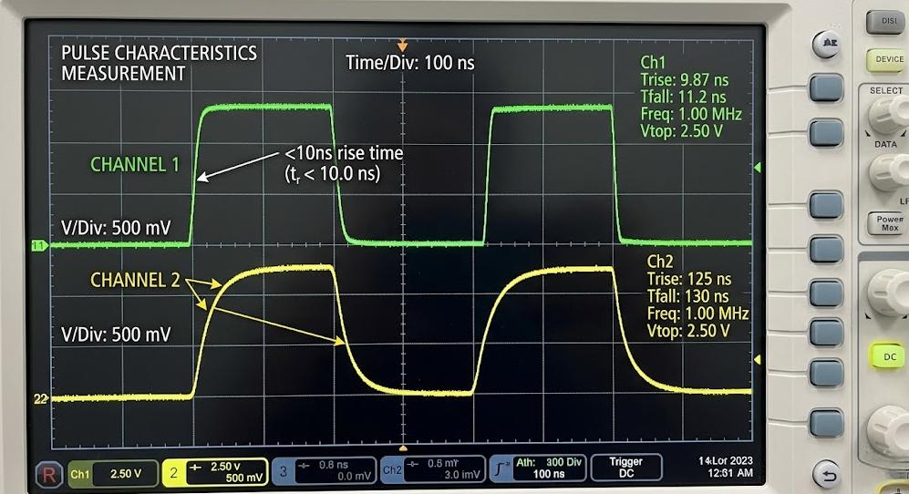
The industry’s demand for higher wafer production hours (WPH) directly translates into the need for faster pulse repetition frequencies. However, if there is a lack of signal integrity, no matter how fast the speed is, it will be of no avail. If the rise time of the driver is too long – for example, within the range of 50 nanoseconds – the shape of the optical pulse will become a “bell-shaped curve” instead of a square wave.
This rounding of the pulses will blur the edges of the detection data. In our tests, upgrading from standard drives to drives with an up/down time of less than 10 nanoseconds significantly improved the edge clarity during high-speed scanning. This rapid switching capability enables the detection tool to operate within mechanical limits without the light signal becoming a bottleneck. This is precisely the difference between processing 30 wafers per hour and 60 wafers per hour.
Industrial-Grade Reliability for Semiconductor Environments
Advanced Thermal Management
The semiconductor factory operates around the clock. During the process of converting direct current to radio frequency electricity, the AOM driver generates a large amount of heat. If the driver overheats, the internal components may drift, resulting in a decrease in the radio frequency output power (with unstable amplitude).
Therefore, we adopted an efficient AB-class amplifier stage and a customized heat dissipation design to address this issue. By maintaining a stable internal temperature, we ensured that the RF amplitude remained constant (with a stability of <±0.5% within 24 hours). This avoided the common “calibration drift” problem, where the detection tool needs to stop operating every few hours and be recalibrated due to changes in laser intensity.
EMC/EMI Shielding and Cleanroom Integration
The cleanroom is an environment with a high density of equipment, including electron beams, precision sensors and high-power motors. The acoustic-optical modulator (AOM) driver must be able to coexist harmoniously with these devices, which means it must have excellent electromagnetic compatibility (EMC).
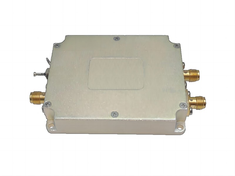
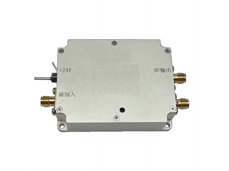
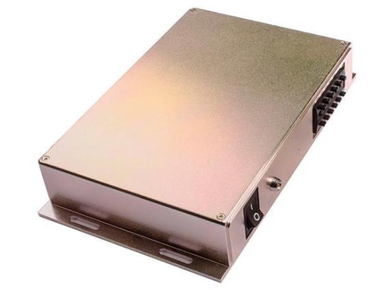
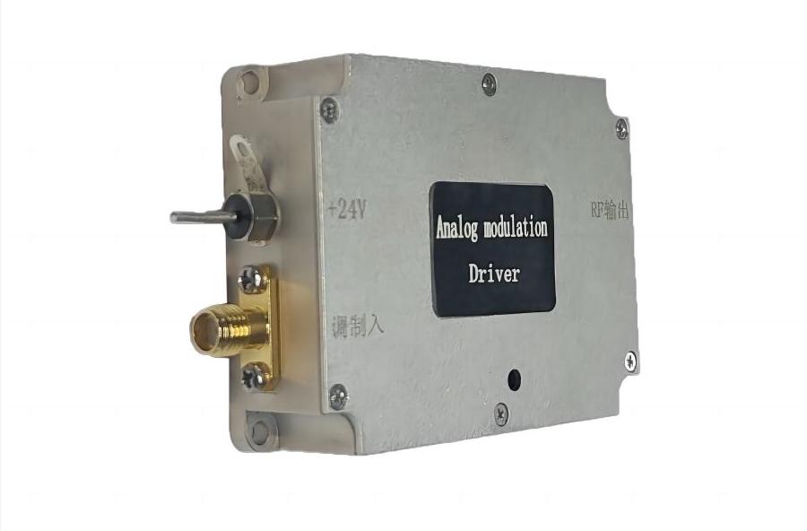
Our drive adopts a CNC precision-machined aluminum housing and is equipped with filtered power input to block electrical noise. This double-layer shielding design can prevent the radio frequency signals of the drive from interfering with the precise low-voltage sensors of the detection tool. It also ensures that the drive itself is not affected by the common strong electromagnetic spikes in the industrial power grid.
VSWR Protection and Crystal Safeguards
Optoacoustic crystals (such as TeO2 or quartz crystals) are among the most expensive components in the optical path. If RF power is reflected due to loose cables or mismatched transducers, the crystals are prone to damage. This reflection can be measured using the Voltage Standing Wave Ratio (VSWR).
A reliable driver must incorporate a VSWR protection circuit. If the driver detects a reflection – possibly due to a technician not tightening the BNC connector or a failure of the crystal transducer – the driver will shut off its RF output within a few microseconds. This “fault protection” mechanism can prevent the reflected energy from damaging the output stage of the driver and the expensive crystal.
Key Considerations When Selecting an AOM Driver Manufacturer
In addition to technical specifications such as rise time and extinction ratio, the actual performance of the inspection tool also depends on the stability of the supply chain and the manufacturer’s ability to support complex integration. Because a driver that works well in a laboratory environment may not meet the strict consistency requirements of high-volume semiconductor production lines. When evaluating OEM partners, the following factors determine whether the hardware can provide long-term value:
- Batch consistency: Each drive must be exactly the same as the “gold unit”. We use automated testing to ensure that the units shipped six months apart have the same phase noise and power curve.
- Customized impedance tuning: The standard 50-ohm match is often not sufficient. Manufacturers should provide customized tuning for your specific crystal to minimize the standing wave ratio (VSWR) and prevent thermal stress.
- Long-term component traceability: The lifecycle of semiconductor tools lasts for ten years; your partner must ensure EOL (End of Life) management to prevent sudden redesign due to outdated chips.
Powering the Next Generation of Chip Manufacturing
In the semiconductor metrology field, the acoustic-optic modulator driver is a core component that directly affects wafer yield. Selecting a driver with nanosecond-level response time and high-frequency stability is a necessary condition to meet the stricter tolerances of 2nm and 3nm processes. By prioritizing the use of industrial-grade RF control, you can reduce false detections and ensure that your detection tools maintain high throughput over many consecutive years of operation.