How to Correctly Use and Operate Fiber Coupled AOM
The fiber-coupled acousto-optic modulator (AOM), also frequently referred to as a fiber-coupled AOM, stands as a sophisticated optical device that leverages the acousto-optic effect to modulate the intensity, frequency, or direction of a light beam propagating within an optical fiber without necessitating any physical disruption to the fiber pathway. By seamlessly integrating a traditional acousto-optic modulator with advanced fiber coupling technology, the fiber-coupled AOM exhibits a compelling array of advantages, including low insertion loss, high extinction ratio, rapid modulation speeds, and excellent compatibility with existing fiber optic systems. These attributes have positioned the fiber-coupled AOM as an increasingly indispensable component across a diverse spectrum of applications, spanning optical communications, fiber optic sensing, laser material processing, and biomedical imaging.
This article delves into the structural composition, operational principles, detailed usage procedures, and essential operational techniques associated with the fiber-coupled acousto-optic modulator, while also highlighting critical considerations for its effective utilization, aiming to provide a comprehensive and practical guide for users.
Structural Composition of Fiber-Coupled AOM
A fully functional fiber-coupled AOM system typically comprises several key components working in concert:
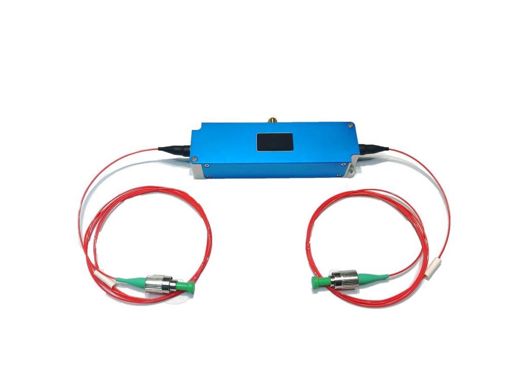
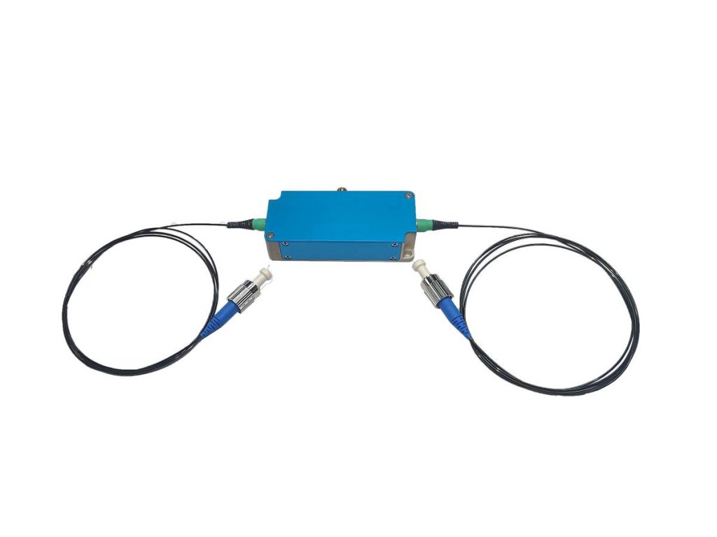
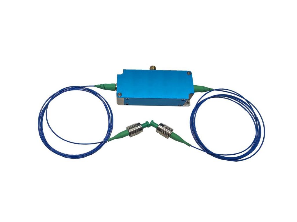
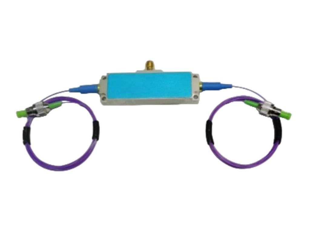
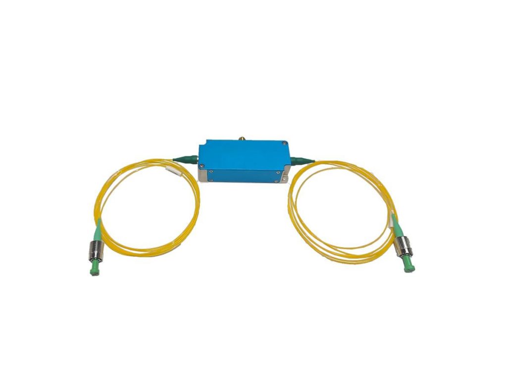
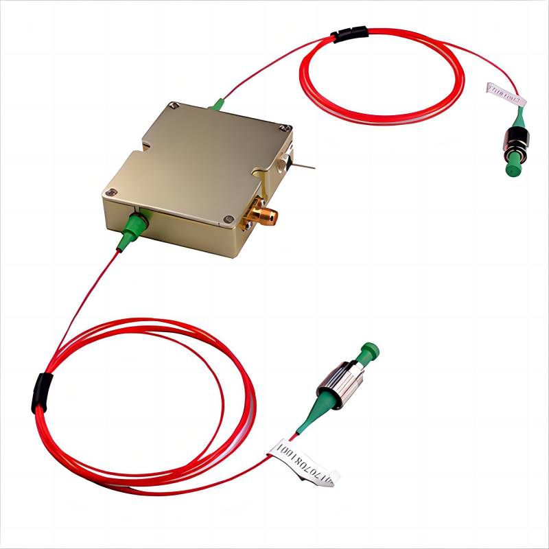
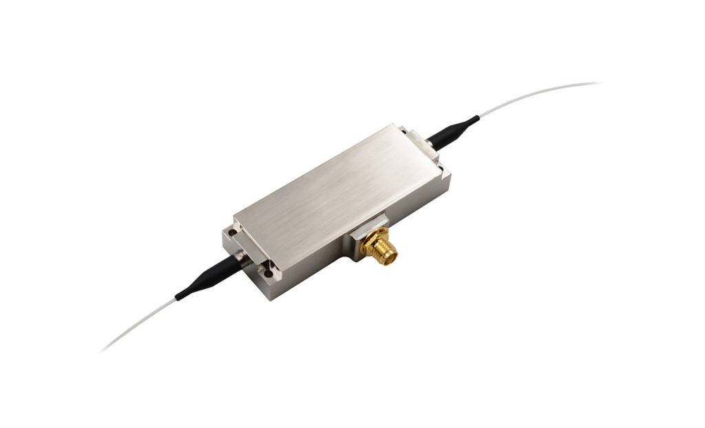
Fiber-Coupled Acousto-Optic Modulator Head: This constitutes the core of the system, housing the critical elements responsible for achieving acousto-optic modulation. These include:
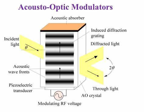
- Acousto-optic Crystal: A specialized transparent medium whose refractive index undergoes periodic variations in response to the propagation of acoustic waves. This crystal forms the fundamental basis for light beam diffraction. Common materials include tellurium dioxide (TeO₂), germanium oxide (GeO₂), and lithium niobate (LiNbO₃).
- Piezoelectric Transducer: The crucial component that converts the input radio frequency (RF) electrical signal into ultrasonic waves. It is typically bonded directly to the acousto-optic crystal to ensure efficient acoustic wave coupling.
- Acoustic Absorber: Designed to absorb the residual acoustic waves propagating through the acousto-optic crystal after interaction with the light beam. This prevents reflected acoustic waves from interfering with the modulation process and ensures a clean modulation signal.
- Fiber Optic Connectors: Standardized optical fiber interfaces, such as FC, SC, or LC connectors, facilitate convenient and low-loss connections to input and output optical fibers.
Radio Frequency (RF) Driver: This electronic module generates the RF signal necessary to drive the piezoelectric transducer, thereby inducing the ultrasonic waves within the acousto-optic crystal. The type of RF driver employed dictates the available modulation modes, such as analog modulation for continuous light intensity control and TTL switching for rapid on/off light beam manipulation.
Power Supply: Provides a stable and reliable electrical power source to the RF driver, ensuring its proper operation. The power supply specifications must be compatible with the requirements of the RF driver.
Signal Generator (Optional): Used when specific modulation patterns are required for the optical signal. It generates various waveforms (e.g., sine waves, square waves, pulse sequences) that control the output of the RF driver, enabling precise manipulation of the light signal.
Fiber Optic Input/Output: Standard fiber optic patch cords or pigtails used to couple the light output from the laser source into the fiber-coupled acousto optic modulator’s input port and to transmit the modulated light signal from the fiber coupled AOM’s output port to subsequent fiber optic devices or systems.
Fiber-Coupled AOM Working Principle
The core operational principle of a fiber-coupled AOM hinges on the acousto-optic effect, a phenomenon involving the interaction between light and sound waves within a specific medium. This process can be broken down into the following sequential steps:
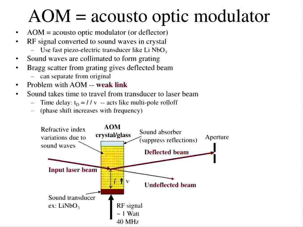
- Acousto-optic Effect: When a radio frequency (RF) electrical signal is applied to the piezoelectric transducer, the piezoelectric material undergoes mechanical deformation, efficiently converting the electrical energy into mechanical vibrations, or ultrasonic waves. These ultrasonic waves propagate through the acousto-optic medium, which is in direct contact with the transducer, at a specific frequency and intensity determined by the applied RF signal.
- Refractive Index Grating: As the ultrasonic waves propagate through the acousto-optic medium, they induce periodic variations in the medium’s density. Since the refractive index of a material is intrinsically linked to its density, these periodic density fluctuations result in a corresponding periodic spatial modulation of the refractive index, effectively creating a dynamic, moving refractive index grating within the crystal. The spatial period or grating spacing of this induced grating is directly related to the wavelength of the acoustic wave.
- Light Beam Diffraction: When the incident light beam propagating through the optical fiber passes through the moving refractive index grating within the acousto-optic medium, it undergoes Bragg diffraction. Bragg diffraction is a specific type of diffraction that exhibits maximum efficiency when the incident light angle (the Bragg angle) and the grating spacing satisfy a particular condition. The characteristics of the diffracted light, such as its intensity, frequency, and direction of propagation, are modulated by the properties of the acoustic wave (e.g., its frequency and intensity). Typically, this interaction results in the generation of a zero-order beam (the undiffracted light) and one or more orders of diffracted beams (deflected light).
- Fiber Coupling: A key feature of the fiber-coupled acousto-optic modulator is its integrated fiber coupling technology. Both the input and output ports are equipped with fiber optic connectors, allowing for direct and convenient connection to the laser source and subsequent fiber optic components without the complexities associated with free-space optical alignment. This design significantly reduces system complexity, minimizes optical losses inherent in free-space propagation, enhances immunity to environmental disturbances, and ultimately improves the overall stability and reliability of the system.
Usage Steps and Operational Techniques of Fiber-Coupled AOM
Proper usage and operational techniques are paramount to ensuring the optimal performance and longevity of a fiber-coupled AOM. The following outlines the detailed usage steps and some crucial operational techniques:
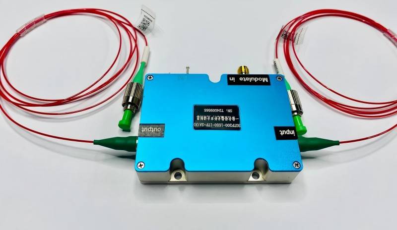
1. Connecting Optical Fibers
Carefully connect the optical fiber output from the laser source to the input port of the fiber-coupled acousto-optic modulator, and connect the input port of the subsequent fiber optic device or system to the output port of the fiber-coupled AOM.
Ensure that the end faces of the fiber optic connectors are meticulously clean and free of dust or debris. Utilize specialized fiber optic cleaning tools if necessary.
Align the connectors precisely, gently insert them, and clockwise tighten the coupling nut, avoiding excessive force that could potentially damage the connectors or the optical fibers.
Verify that the optical fibers are not subjected to excessive bending or kinking, as this can lead to increased optical losses and even fiber breakage.
2. Connecting the RF Driver
Use a suitable RF coaxial cable to securely connect the output port of the RF driver to the RF input port of the fiber-coupled acousto optic modulator. Ensure a firm and reliable connection to prevent signal degradation or loss.
3. Connecting the Power Supply
Connect the RF driver to a power supply that meets its specified voltage and current requirements. Turn on the power supply, ensuring that the voltage setting matches the driver’s input voltage.
4. Inputting Control Signals (If Required)
If specific modulation of the optical signal is desired, such as analog or pulse modulation, connect the output of the signal generator to the modulation input port of the RF driver.
Configure the output parameters of the signal generator, including the desired waveform and frequency, according to the application requirements.
5. Setting the RF Driver
Based on the specifications of the fiber-coupled acousto-optic modulator and the application requirements, configure the key parameters of the RF driver, such as the RF frequency and output power.
Selecting the appropriate RF frequency is critical. Consult the modulator’s datasheet to identify the optimal operating frequency that yields the highest diffraction efficiency. Different modulators may have varying optimal operating frequencies.
6. Adjusting Drive Power
The intensity of the first-order diffracted light transmitted through the acousto-optic modulator can be controlled by adjusting the output power of the RF driver.
Increasing the RF power generally leads to an increase in the intensity of the first-order diffracted beam. However, it is crucial to never exceed the maximum RF drive power specified in the modulator’s datasheet to prevent damage to the device.
In practical applications, carefully adjust the drive power to achieve the desired output light intensity while staying within the safe operating limits.
7. Selecting the Appropriate Diffraction Order
Choose the appropriate diffraction order for the output light based on the specific application requirements.
The zero-order beam represents the undiffracted light, and its intensity decreases as the RF power increases.
The first-order diffracted beam is the light that has been modulated by the acoustic wave, and its intensity typically increases with increasing RF power (within a certain range). Intensity modulation applications commonly utilize the first-order diffracted light as the output.
In some specialized applications, other diffraction orders might be utilized. Typically, spatial filters are employed in the optical path to isolate the desired diffraction order selectively.
8. Monitoring Output Light
Utilize a power meter or other suitable photodetector to continuously monitor the optical power and modulation characteristics of the output light from the fiber coupled AOM.
Based on the measured results, fine-tune the parameters of the RF driver and the input signal to achieve optimal modulation performance.
9. Observing Safety Precautions
As fiber-coupled acousto-optic modulators are typically used in conjunction with laser systems, it is imperative to strictly adhere to all relevant laser safety protocols.
Always wear appropriate laser safety eyewear that is specifically designed for the wavelength of the laser being used. Avoid direct exposure of the eyes and skin to the laser beam.
Ensure that the work area is properly secured to prevent accidental exposure to the laser beam.
Important Considerations During Fiber-Coupled AOM Running
To ensure the long-term stable operation and optimal performance of the fiber-coupled acousto-optic modulator, the following important considerations must be taken into account during usage:
- Consult the Datasheet: Before the initial use, thoroughly review the datasheets for both the fiber-coupled acousto-optic modulator and the RF driver. Gain a comprehensive understanding of their electrical and optical characteristics, maximum power handling capabilities, recommended operating frequency, and operating wavelength range. This is fundamental for correct operation and preventing device damage.
- Avoid Excessive Drive Power: Never apply an RF drive power exceeding the maximum limit specified in the modulator’s datasheet. Overdriving the modulator can lead to overheating of the acousto-optic crystal, generation of nonlinear effects, and potentially permanent damage to the device.
- Optimize Fiber Connections: Maintaining clean fiber optic connectors is of paramount importance. Dust and debris on the connector end faces can obstruct light transmission, leading to increased optical losses and even damage to the connector surfaces. Regularly clean the fiber optic connectors and ensure stable and reliable connections to minimize optical losses and prevent accidental disconnections.
- Select a Compatible RF Driver: Choose an RF driver that is compatible with the fiber-coupled AOM in terms of modulation type (e.g., analog, TTL, pulse), modulation bandwidth, and output power capabilities. The performance of the RF driver directly impacts the achievable modulation characteristics.
- Consider the Operating Wavelength: Ensure that the wavelength of the laser source being used falls within the specified operating wavelength range of the fiber-coupled acousto optic modulator. Using a laser with a wavelength outside this range can result in significantly reduced modulation efficiency or complete failure of the device to operate correctly.
- Temperature Control: For certain high-power applications, the acousto-optic crystal can absorb a portion of the RF energy, leading to heat generation. In such cases, precise temperature control of the modulator may be necessary to maintain stable and reliable performance. Temperature control modules or heat sinks can be employed to keep the modulator within its optimal operating temperature range.
The fiber-coupled acousto-optic modulator represents a highly efficient, compact, and easily integrable optical modulation device that plays an increasingly vital role in modern optoelectronic technologies. A thorough understanding of its structural composition and operational principles, coupled with adherence to proper usage steps, operational techniques, and critical considerations, is essential for maximizing the performance and extending the lifespan of this sophisticated component.