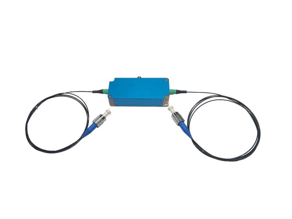
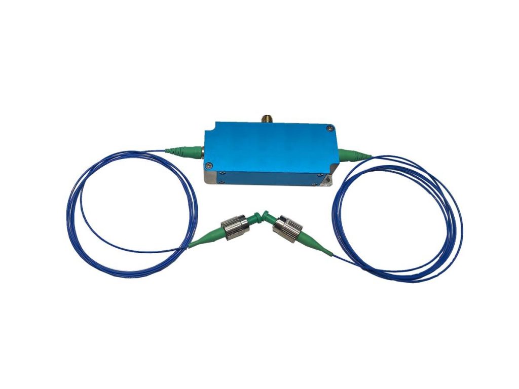
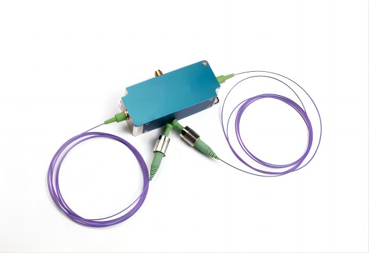
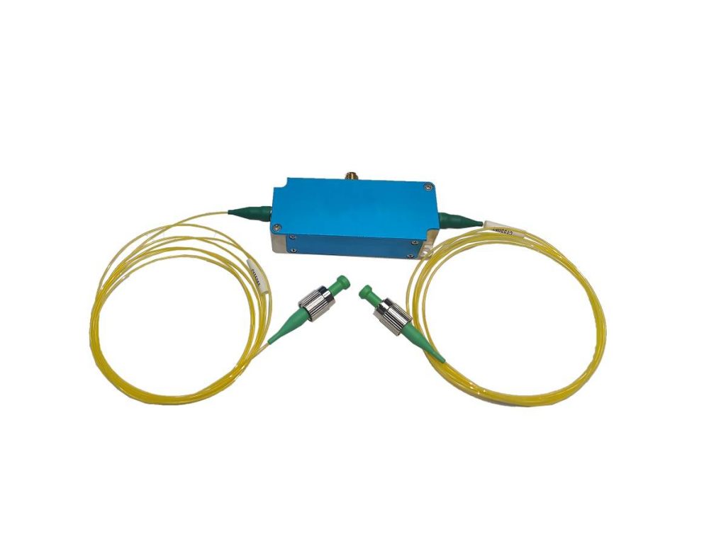
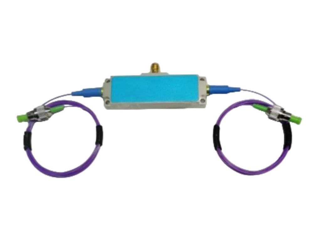
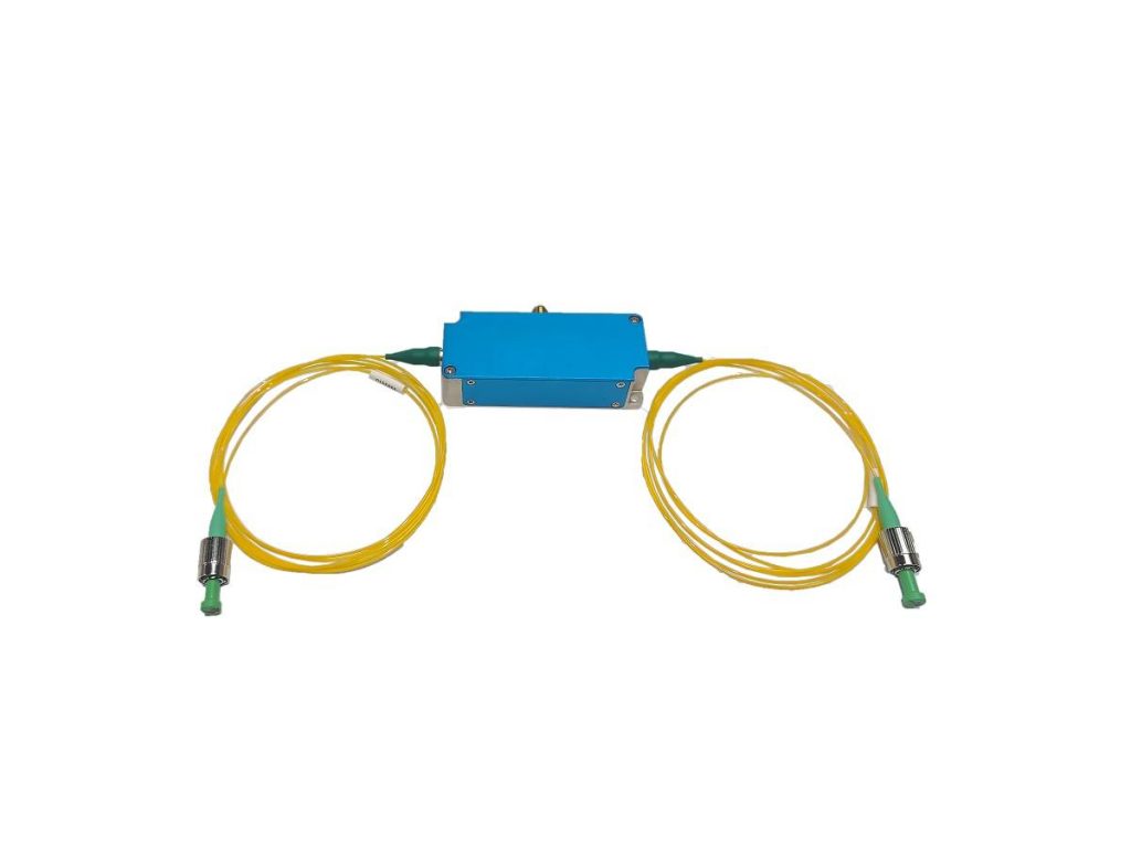
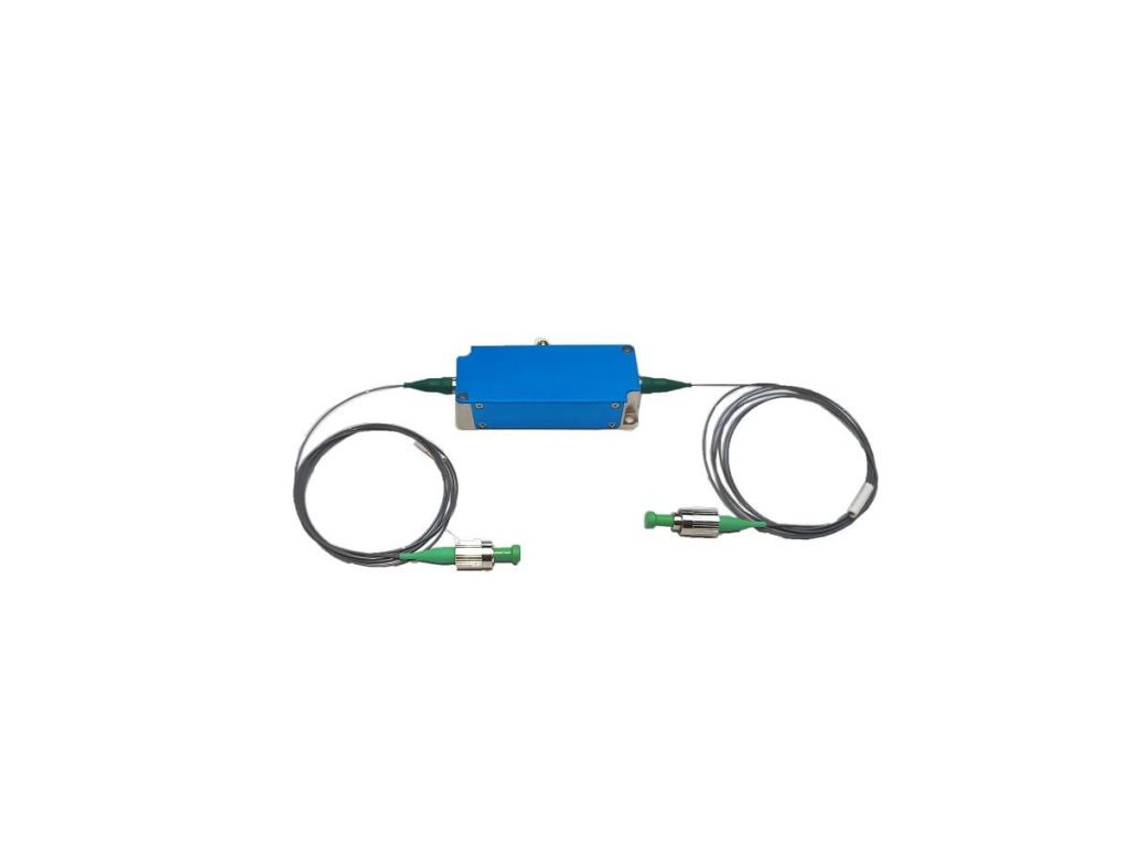
461nm Fiber AOM Series
Acousto optic modulator is a kind of product that uses the principle of acousto-optic interaction to modulate the intensity and shift the frequency of the laser. The wavelength range is from visible light to infrared region. It adopts all metal structure design, compact and solid sealed packaging structure, and innovative packaging technology, which ensure high reliability and temperature stability.
Characteristics of 461nm Fiber AOM Series
- Short response time
- Low insertion loss
- High extinction ratio
- High-temperature stability and reliability
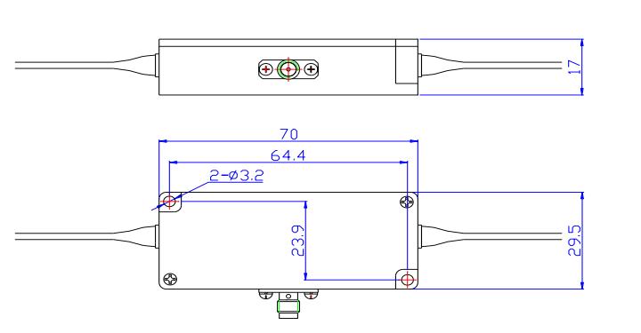
- Small size
Applications of 461nm Fiber AOM Series
- Q-switched fiber laser
- Laser Doppler coherent application
- Ultra-fast laser frequency reduction menu
- Linear frequency modulation
Ordering Information of 461nm Fiber AOM Series
This indicator is a typical optical wavelength indicator, and other wavelengths and frequencies can be selected
| Parameter | Unit | SGTF100-461-1P | SGTF200-461-1P |
| Insertion loss | dB | <3 | <3.5 |
| Rise time | ns | <50 | <15 |
| shift frequency | MHz | 100 | 200 |
| 3dB frequency shift bandwidth | MHz | >20 | >40 |
| Wavelength | nm | 461 (Typical value) | |
| Optical power | W | ≤0.1 | |
| Polarization-dependent loss(SM device) | dB | ≥50 | |
| Polarization extinction ratio (PM device) | dB | ≥20 | |
| Polarization dependent loss(SM device) | dB | <0.5 | |
| Driving power | W | <1 | |
| Fiber type | – | PM460(PM) | |
| Optical fiber connector | – | FC/APC | |
| RF input joint | – | SMA | |
| Fiber length | m | >1 | |
| Input impedance | Ω | 50 | |
| VSWR | – | <1.3:1 | |
| Package | – | FA | |
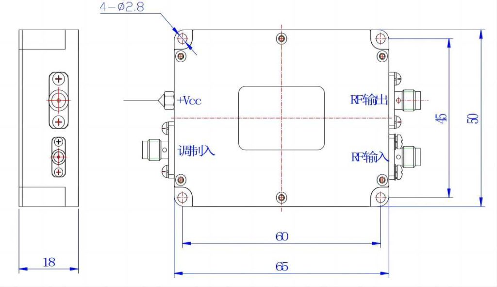
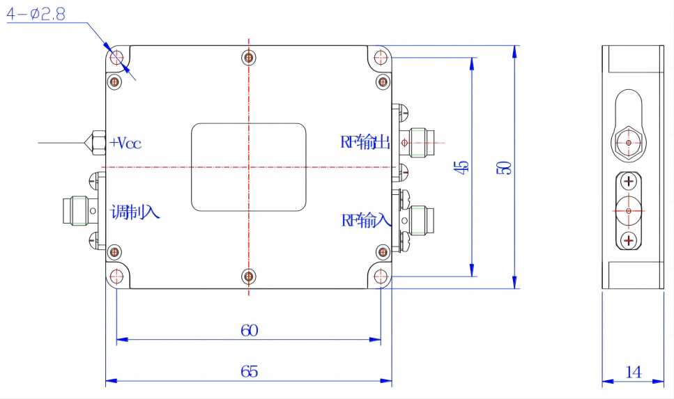
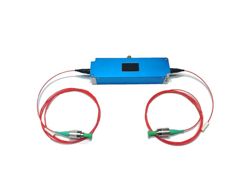
Low-power N-type Acousto Optic Driver for 461nm Fiber AOM Series
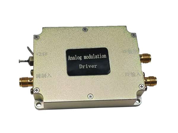
Acousto-optic driver is an RF driver that provides supporting functions for acousto-optic device products. It is applicable to acousto-optic modulators and frequency shifter products with driving power less than 3W. The RF signal generated by the driver is used to generate ultrasonic waves in the crystal of the acousto-optic device. The frequency and intensity of the RF signal applied will determine the degree to which the beam is modulated, deflected, or tuned. The drive has good heat dissipation, and the use of a matched drive will bring better temperature stability.
| Supporting Drive | Model (SGXXXX-33-N-ab) “X” – use “Y” for frequency shift function, and “T” for modulation function; “XXX” – operating frequency “33” refers to RF output power; “N” indicates the package type; “A” – use “1” for power supply voltage 24V, “2” for power supply voltage 12V; “b” – use “D” for digital TTL modulation, and “A” for analog modulation. | |
| SGT100-33-N2-1D | SGT200-33-N-1D | |
| SGT100-33-N2-1A1 | SGT200-33-N-1A1 | |
| SGT100-33-N2-1A5 | SGT200-33-N-1A5 | |
Performance of Low-power N-type Acousto Optic Driver on Fiber AOM
- Small size
- Fast response time
- Low power consumption
- High-temperature stability and reliability
| Item | Unit | Performance | |
| Specifications of the modulation input interface | |||
| Modulated signal input | – | Digital modulation (high level 3.3-5V; low level 0-0.2V@1k Ω) | |
| Analog modulation (A1: 0-1V@50 Ω) | |||
| Analog modulation (A5: 0-5V@1k Ω) | |||
| Modulated signal input impedance | Ω | – | |
| Interface | – | SMA | |
| RF output interface specification | |||
| Output signal frequency | MHz | 100 | 200 |
| Frequency stability | ppm | 20 ( 1 Special) | |
| Output signal power | W | <2 | |
| Rise and fall time | ns | <25 | <10 |
| Switching ratio | dB | ≥60 | |
| Harmonic suppression ratio | dBc | >25 | |
| Signal output standing wave ratio | – | ≤1.3 | |
| Interface | – | SMA | |
| Complete machine specification | |||
| Maximum power consumption | W | 10 | |
| Working voltage | Vdc | 24±1V(Optional 12±0.5) | |
| Power interface | Through core capacitance (core wire is connected to positive, solder lug is connected to negative) | ||
| Package | – | N/N2 | |