What’s the Difference Between AOM Driver and Radio Frequency Amplifier?
The world of electronics and photonics utilizes a vast array of specialized components to achieve specific functions. Two such components, the AOM driver (also known as RF driver) and the radio frequency (RF) amplifier, may seem similar at first glance due to their involvement with radio frequencies. However, a closer look reveals distinct purposes and functionalities for each. This article delves into the inner workings of AOM drivers and RF amplifiers, highlighting their key differences in terms of function, application, and processed signals.
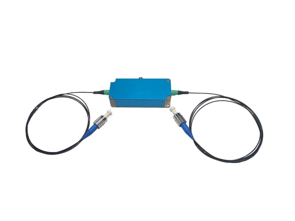
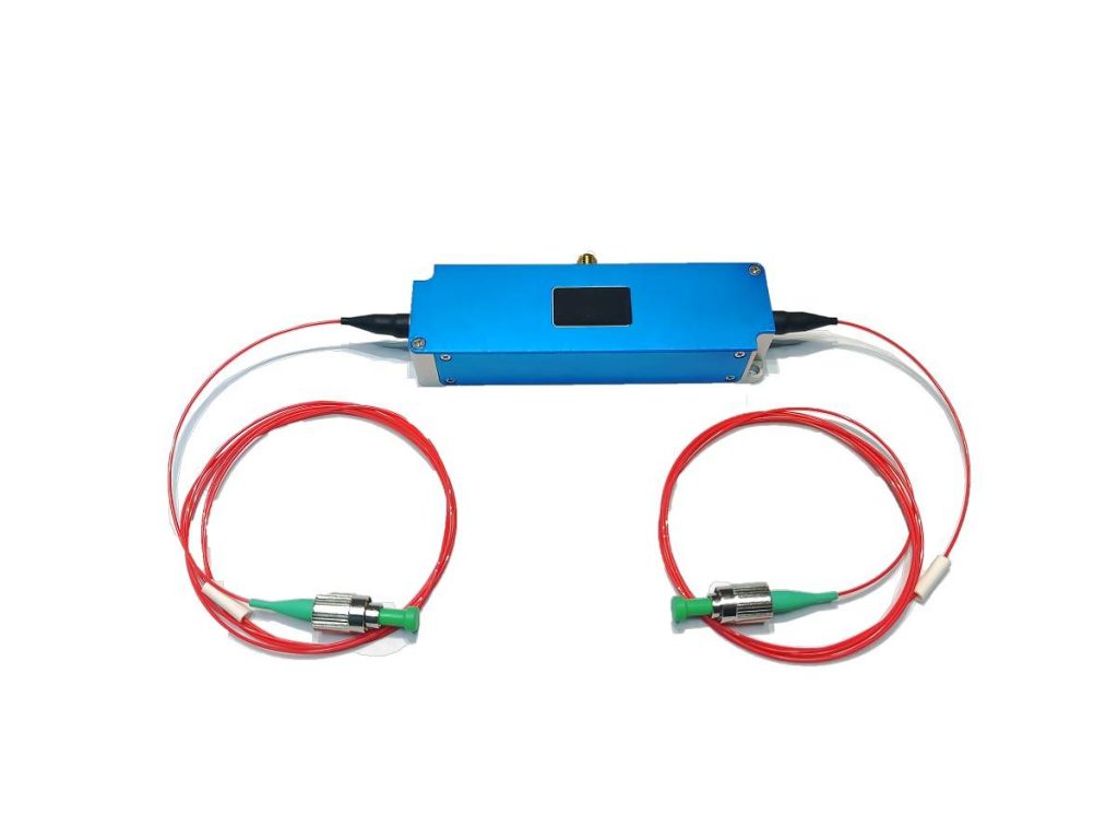
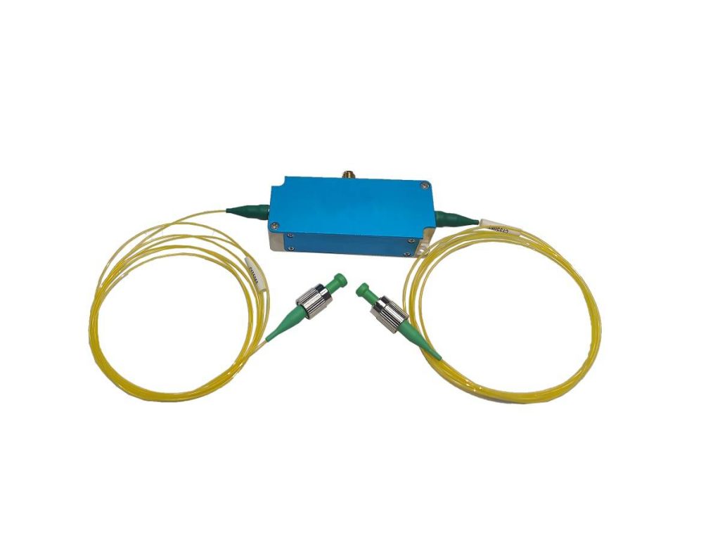
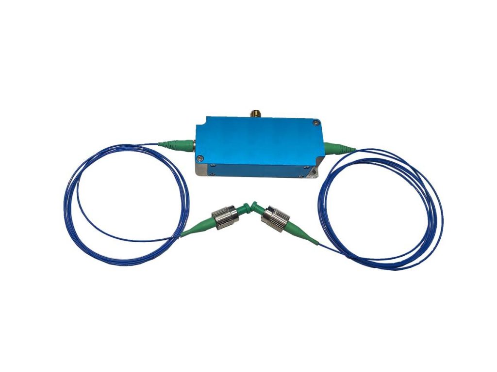
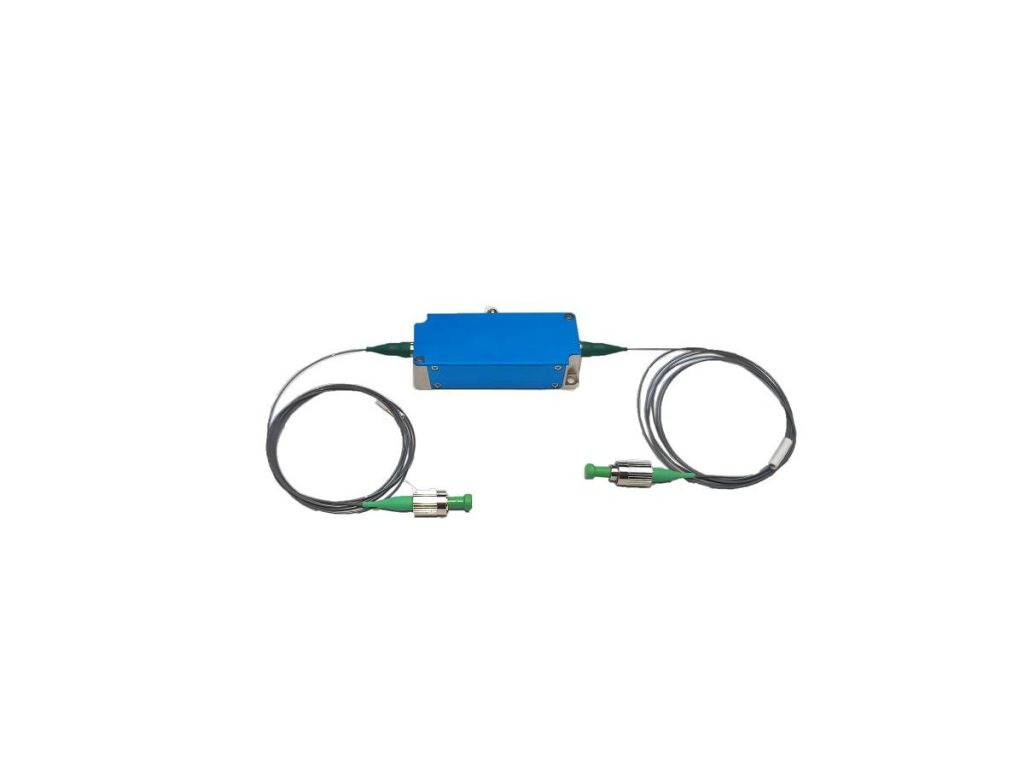
What are AOM Devices?
Acousto-optic modulators (AOMs) are fascinating devices that manipulate light using sound waves. They consist of a crystal through which an electrical signal drives a piezoelectric transducer. The transducer converts the electrical signal into an acoustic wave (sound wave) that propagates through the crystal. This acoustic wave interacts with the light beam passing through the crystal, causing various effects depending on the specific application. AOMs can be used to modulate the intensity (brightness), frequency, or direction of a light beam.
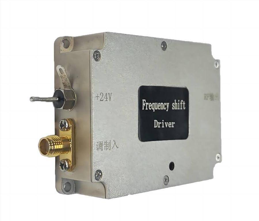
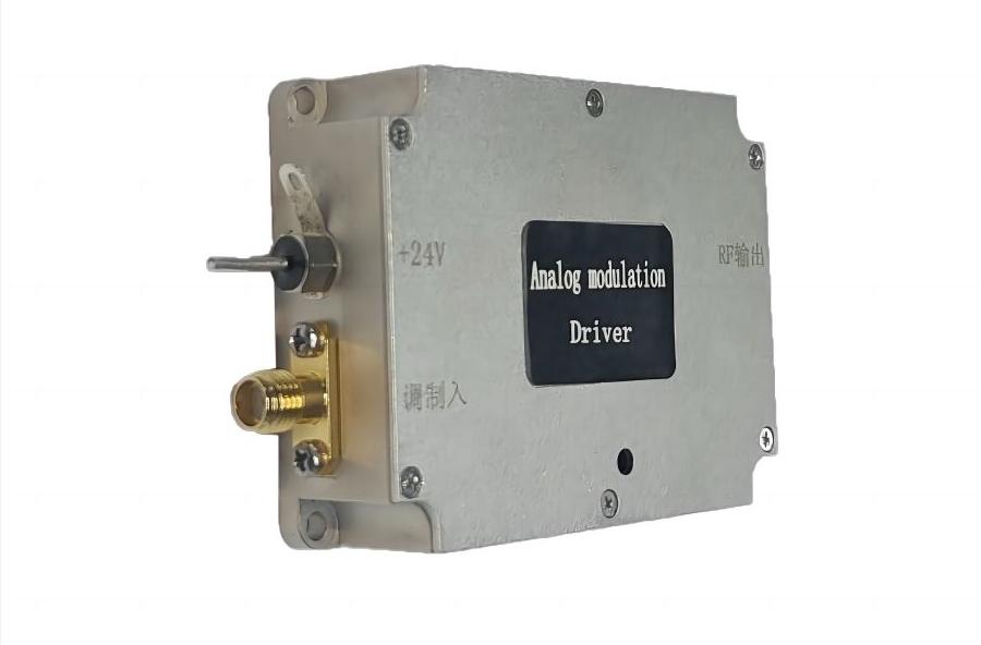
What is the AOM Driver?
An AOM driver, also known as an RF driver, is an electronic circuit specifically designed to generate a precise electrical signal, either at a fixed frequency or with the ability to vary the frequency. This signal serves as the driving force for the AOM device.
The Function of AOM Drivers
The AOM driver operates in a multi-step process. First, it generates the electrical signal with the desired frequency characteristics. This signal can be a continuous wave (CW) for a fixed frequency or a modulated signal for varying frequencies. Next, the driver transmits this electrical signal to the transducer within the AOM.
The magic happens at the transducer. This component utilizes the principle of the piezoelectric effect. When the electrical signal interacts with the transducer, the piezoelectric material undergoes a minute physical deformation. This deformation, in turn, triggers the creation of an acoustic wave within the AOM crystal. The frequency of the acoustic wave directly corresponds to the frequency of the electrical signal generated by the driver.
The generated acoustic wave propagates through the AOM crystal, interacting with the light beam passing through it. This interaction alters specific properties of the light beam, depending on the desired operation. For instance, the intensity of the light beam can be modulated by the acoustic wave, allowing the AOM to function as a light intensity controller. Alternatively, the acoustic wave can cause a shift in the frequency of the light beam, enabling the AOM to act as a frequency shifter.
The Applications of AOM Drivers
AOM drivers find applications in various fields that involve light manipulation. Some common applications include:
- Laser beam modulation: AOM drivers are used to control the intensity or pulse width of laser beams, which is crucial in laser processing, material characterization, and free-space communication.
- Frequency shifting: AOM drivers can be used to shift the frequency of a light beam by a precise amount. This finds application in areas like spectroscopy, where specific frequencies of light are used to analyze materials.
- Optical switching: By rapidly turning the AOM on and off, the light beam can be quickly switched on and off. This property is utilized in applications like optical signal processing and laser beam deflection.
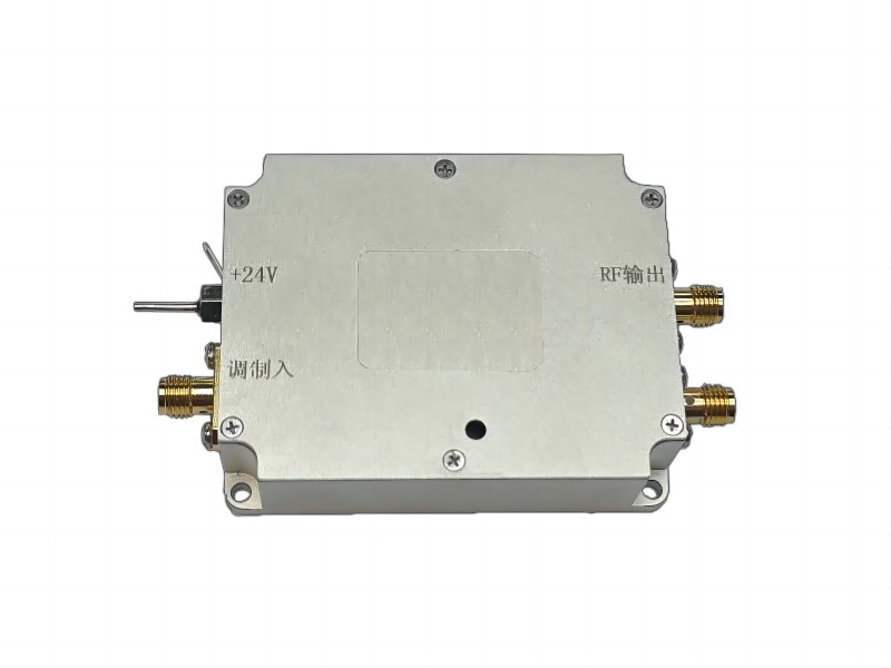
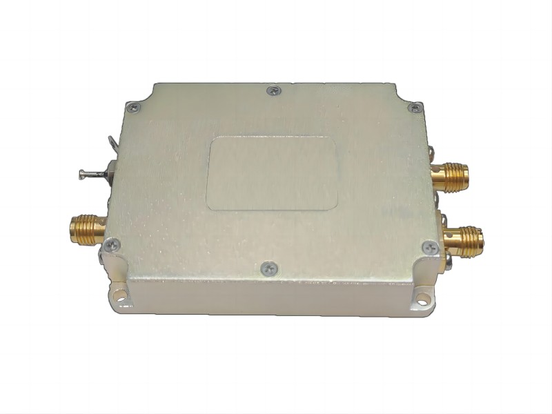
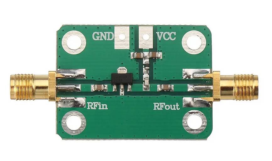
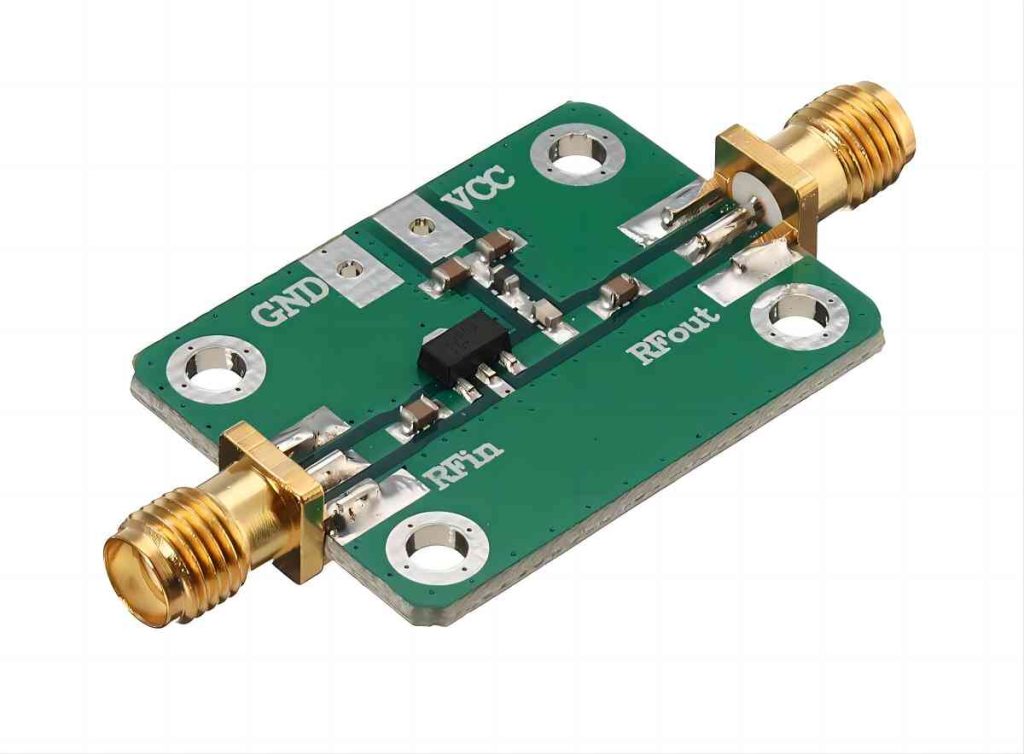
What is the RF Amplifier?
Radio frequency (RF) amplifiers are workhorses in the realm of electronic communication. Their primary function is to amplify, or strengthen, an existing RF signal. RF signals are electrical signals that oscillate at very high frequencies (typically ranging from tens of kilohertz to tens of gigahertz). These signals are crucial for various applications like radio and television broadcasting, mobile phone communication, and radar systems. However, they often require amplification before transmission to overcome signal losses due to distance or resistance in cables. Here’s where RF amplifiers come in – they take a weak RF signal and boost its power level, enabling it to travel longer distances or overcome signal degradation.
The Function of RF Amplifier
The core function of an RF amplifier is straightforward. It receives a weak RF signal as input and employs electronic components like transistors to amplify the signal’s power level. This amplification process typically involves increasing the amplitude (voltage or current) of the signal while preserving its frequency characteristics.
RF amplifiers are ubiquitous in numerous electronic devices. In communication systems like radio and television broadcasting, they play a vital role in amplifying weak baseband signals before conversion to a carrier frequency for transmission over long distances. Similarly, in radar systems, RF amplifiers boost the power level of the transmitted signal to ensure sufficient range and detection capability.
Types of RF Amplifiers
There are various types of RF amplifiers, each with its own characteristics and applications. Some common classifications include:
- Class A amplifiers: These provide linear amplification but are less efficient in terms of power consumption.
- Class B amplifiers: Offer higher efficiency but introduce distortion in the amplified signal.
- Class C amplifiers: Achieve high efficiency but require additional circuitry to combine the output with another signal to recover the original signal information.
The specific type of RF amplifier chosen depends on the desired balance between amplification level, linearity, and efficiency. Here’s a breakdown of some key factors influencing the selection:
- Amplification Level: This refers to the increase in signal strength achieved by the amplifier. It is usually expressed in decibels (dB). Applications requiring a significant boost in signal power, like radar transmitters, may opt for Class C amplifiers despite their distortion characteristics. Conversely, applications demanding high fidelity, such as radio frequency test equipment, may prioritize Class A amplifiers for their linear amplification, even if it comes at the cost of lower power efficiency.
- Linearity: This refers to the amplifier’s ability to maintain the original waveform of the input signal during amplification. Ideally, the amplified output should be a replica of the input signal with increased power. However, some amplifier designs introduce distortion into the output signal. Class A amplifiers offer the highest degree of linearity, making them suitable for applications where signal fidelity is critical. However, Class B and Class C amplifiers may introduce distortion due to their operating bias points. Techniques like pre-distortion and linearization circuits can be employed to mitigate distortion in these amplifiers, but they add complexity to the design.
- Efficiency: This metric indicates how effectively the amplifier converts DC power from its supply into usable RF output power. Class C amplifiers achieve the highest efficiency by operating the transistors for a smaller portion of the input signal cycle. This reduces power dissipation within the transistor itself, leading to better efficiency. However, this efficiency comes at the cost of increased distortion. Class A amplifiers, on the other hand, offer lower efficiency due to continuous current flow through the transistors, even during periods with no input signal. Class B amplifiers occupy a middle ground, offering a balance between efficiency and linearity.
Key Differences Between AOM Drivers and RF Amplifiers
Having explored the functionalities of both AOM drivers and RF amplifiers, it’s time to delve into their key distinctions, here is a table summarizing the differences as follows:
| Aspect | AOM Drivers | RF Amplifiers |
| Function | Generate precisely controlled electrical signals, converted into acoustic waves within AOM device, interacts with light beam | Manipulate power level of existing RF signal, amplify strength of signal while maintaining frequency characteristics |
| Applications | Laser processing, optical communication, spectroscopy | Electronic communication, signal processing, radio and television broadcasting, radar systems |
| Output Signal | Acoustic waves interacting with light beam | Amplified electrical signals in the radio frequency range |
Conclusion
AOM drivers and RF amplifiers, despite their involvement with electrical signals, serve distinct purposes within their respective technological domains. AOM drivers act as the maestros in the world of optoelectronics, generating precise electrical signals to manipulate light properties through AOM devices. In contrast, RF amplifiers are the workhorses of electronic communication and radar systems, faithfully amplifying the power level of RF signals to ensure strong transmission and reliable reception. Understanding these distinctions is crucial for selecting the appropriate component when working with light or radio frequency signals in various technological applications.