Fiber Acousto-Optic Modulators: A Comprehensive Guide
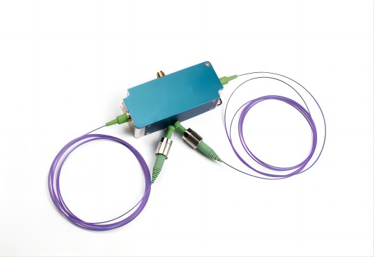
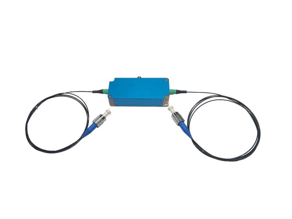
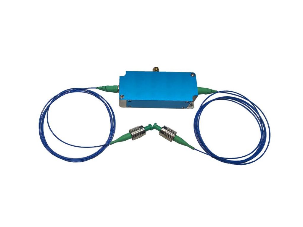
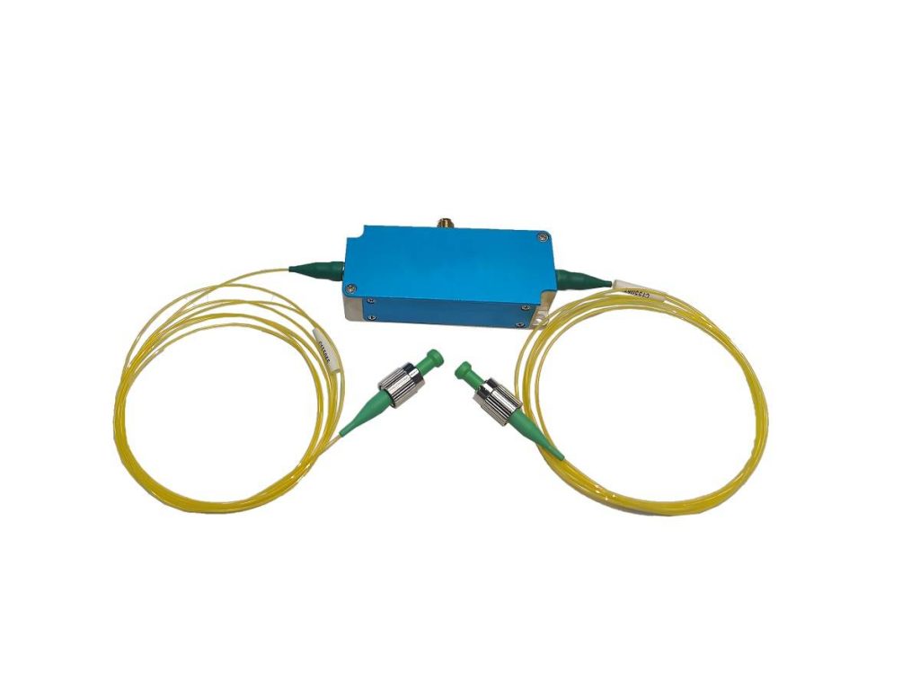
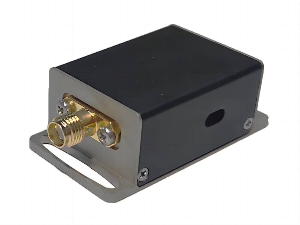
Fiber acousto optic modulators (FAOMs) are fascinating devices that bridge the gap between the worlds of sound and light. They play a crucial role in various applications, from high-speed telecommunications to laser beam shaping. But for those new to FAOMs, their inner workings might seem shrouded in mystery. This article by Smart aims to demystify these intriguing devices by delving into three key aspects: their operational wavelength range, the driving requirements for effective operation, and how temperature fluctuations can impact their performance. By understanding these fundamental aspects, you’ll gain valuable insights into the capabilities and considerations surrounding FAOMs. Whether you’re a seasoned engineer or just starting to explore the world of fiber optics, this article will equip you with the knowledge to navigate the selection and utilization of these powerful modulators.
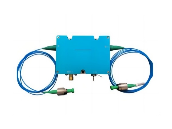
What Is the Wavelength Range of Operation for a Fiber Acousto-Optic Modulator?
The operational wavelength range of a Fiber Acousto Optic Modulator (FAOM) depends on several factors, but it generally covers a broad spectrum, typically ranging from the visible to the infrared region. Here’s a detailed breakdown:
Factors Affecting Wavelength Range
| Material Properties | The materials used in the FAOM, specifically the core fiber and the acoustic medium, are critical. |
| Core Fiber | Different fiber core materials have varying transmission windows depending on their composition. Common choices include silica fibers for the visible and near-infrared (NIR) range, and specialty fibers like chalcogenide glasses for the mid-infrared (MIR) region. |
| Acoustic Medium | The acoustic medium, which can be either solid or liquid, also has an impact on the wavelength range. Different materials have different acoustic velocities and interaction lengths with light, which influences how well they modulate specific wavelengths. |
| Design Considerations | The operational range can be impacted by the FAOM’s design. Acoustic mode selection and waveguide geometry can influence how light interacts with sound waves at various wavelengths. |
Typical Wavelength Ranges
| Wavelength Ranges | Explanation | Examples of Products Provided by Smart |
| Visible Spectrum (400 nm – 750 nm) | FAOMs can be designed to operate in the visible range, making them ideal for use in displays or high-speed optical communication systems. | 461nm Fiber AOM Series, 532nm Fiber AOM Series |
| Near-Infrared (NIR) Spectrum (750 nm – 1400 nm) | This is a popular operational range for FAOMs due to the abundance of high-quality silica fibers with low loss in this area. Applications include telecommunication signal modulation and optical sensing. | 780nm Fiber AOM Series,1064nm Fiber AOM Series,1064nm High Power Fiber AOM Series |
| Mid-Infrared (MIR) Spectrum (1400 nm – beyond) | Materials such as chalcogenide glasses can be used to create specialized FAOMs that operate in the mid-infrared range. These have applications in spectroscopy, laser beam shaping, and thermal imaging. | 1550nm Fiber AOM Series,1650nm Fiber AOM Series,2000nm Fiber AOM Series |
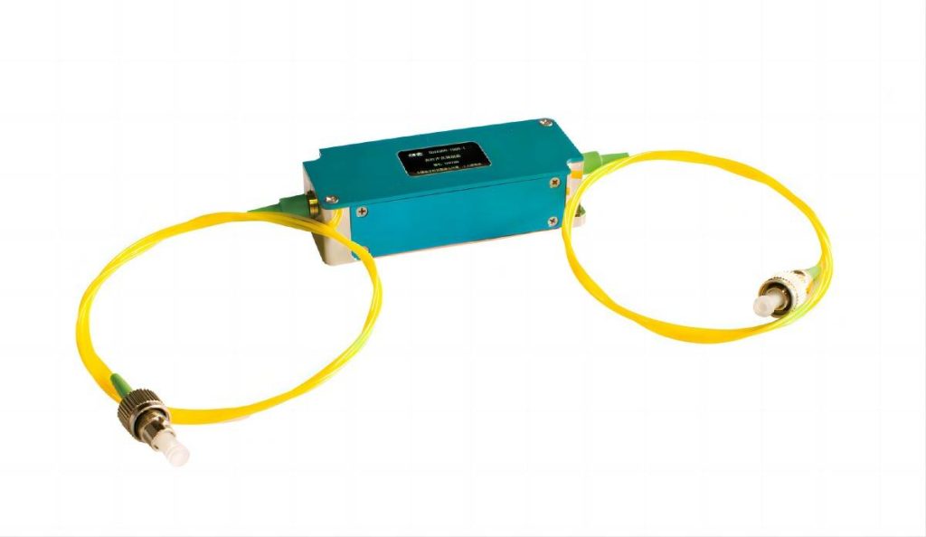
What Are the Driving Requirements for a Fiber Acousto-Optic Modulator?
A FAOM relies on an external Radio Frequency (RF) signal to control the sound waves that modulate the light. Here’s a detailed breakdown of the driving requirements:
RF Signal Characteristics
- Power Level: The RF signal needs to have sufficient power to generate effective acoustic waves within the FAOM. The specific power level required depends on the FAOM design, material properties, and desired modulation depth.
- Frequency: The frequency of the RF signal determines the frequency of the generated sound waves, which in turn defines the modulation frequency of the light. By varying the RF frequency, you can control the speed at which the light is modulated.
- Impedance: The FAOM’s RF input has a specific impedance, that must be matched to the impedance of the driver circuit for optimal signal transfer and minimum reflection. Impedance mismatch can cause power loss and lower modulation efficiency.
Driver Circuit
- Amplification: The RF signal from a typical source may need to be amplified to reach the FAOM’s required power level. An RF driver circuit provides this amplification while also ensuring proper impedance matching with the FAOM.
- Control Interface: The driver circuit may provide various control options, such as voltage control or digital inputs, to adjust the RF signal characteristics (frequency, power) for the desired modulation behavior.
Additional Considerations
- Biasing Voltage: Some FAOMs may require a separate biasing voltage to optimize their performance. This biasing voltage can influence acoustic wave generation and modulation efficiency.
- Temperature Effects: Temperature variations can affect FAOM performance. To ensure reliable modulation, the RF driver circuit should be designed to operate in the FAOM’s specified temperature range.
Choosing the Right Driver
- Manufacturer Recommendations: Many FAOM manufacturers recommend driver circuits that are both compatible and optimized for their devices. These drivers are intended to provide the necessary power, impedance matching, and control features to ensure peak performance.
- Custom Driver Design: For specialized applications or high-performance requirements, you might consider designing a custom RF driver circuit tailored to the specific FAOM and desired modulation characteristics.
There are two main types of standardized drivers to choose from SMART SCI&TECH: RF drivers and broadband RF amplifiers, with a wide range of RF frequency choices. We are honored to serve you, whether through standardized drives or customized services. By understanding these driving requirements and carefully selecting or designing the appropriate RF driver circuit, you can ensure the effective and reliable operation of your FAOM for light modulation applications.
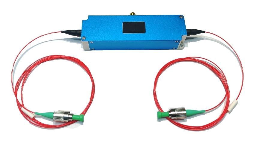
How Does Temperature Affect the Performance of a Fiber Acousto-Optic Modulator?
Temperature can affect the performance of a Fiber Acousto-Optic Modulator (FAOM) in several ways. Here’s a detailed breakdown of the key aspects:
Impact on Material Properties
The acoustic velocity within the FAOM’s material (usually a solid or liquid) varies with temperature. This variation affects the interaction of sound waves and light, which may result in a shift in the modulation’s center frequency. A higher temperature may cause sound waves to travel faster, yielding a higher center frequency for light modulation. Temperature fluctuations can cause FAOM components to expand and contract. This can result in slight changes to the physical dimensions of the acoustic medium or waveguide, affecting how light propagates through the device. These changes may result in variations in insertion loss (the amount of light signal lost) or even mode coupling effects, which will affect overall modulation efficiency.
Consequences of Temperature Fluctuations
As previously stated, changes in acoustic velocity due to temperature can cause the center frequency of modulated light to drift. This can be problematic in applications that require precise control over the modulation frequency. Thermal expansion and material changes can reduce light modulation efficiency. This results in a lower modulation depth, which means that the intensity variation of the output light signal may be less noticeable. Temperature variations can cause increased insertion loss, indicating that the light signal is attenuated as it travels through the FAOM. This may limit the overall power of the modulated signal.
Minimizing Temperature Effects
- Temperature Control: For optimal performance, the FAOM should be operated in a temperature-controlled environment. Temperature stabilization chambers or heat sinks may be used to keep the operating temperature constant.
- FAOM Material Selection: Choosing an FAOM made from materials with low thermal sensitivity in relevant parameters (acoustic velocity, refractive index) can help reduce performance drift. It is critical to consult manufacturer specifications regarding material properties and temperature ratings.
- Driver Circuit Design: The RF driver circuit can use temperature compensation techniques. This could entail adjusting the driving frequency based on temperature readings to compensate for potential center frequency shifts in the FAOM.
Conclusion
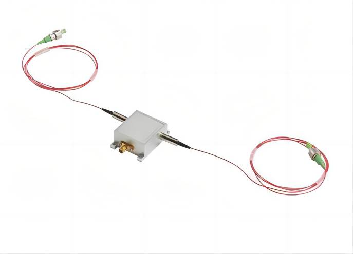
As we’ve explored, FAOMs offer a versatile and powerful approach to light modulation. However, unlocking their full potential requires careful consideration of several factors. The operational wavelength range determines their suitability for specific applications, from visible light manipulation to mid-infrared spectroscopy, and so on. By carefully considering these aspects and selecting the right FAOM for your specific wavelength needs, driving capabilities, and operating environment, you can ensure reliable and efficient light modulation. With this knowledge in hand and consulting opto acoustic modulator supplier Smart for more information, FAOMs can become a valuable tool in your photonics toolbox, enabling innovative advancements in various fields.

