How Does The RF Drive Frequency Of an AOM Affect The Modulation Bandwidth?
Although a high-bandwidth AOM was chosen, when actually performing signal modulation, the waveform seemed to be distorted as if it had been “distorted”. I was full of expectations to increase the RF frequency, but the system response speed decreased instead of rising. Where on earth is the problem? In fact, the relationship between RF drive frequency and modulation bandwidth is far more complex than we imagine. Incorrect configuration is like putting an invisible shackle on the system, directly leading to performance bottlenecks. Let’s break down the three key issues that engineers most frequently encounter to help you truly understand how to optimize the modulation bandwidth of acousto-optic modulator.

Key Question 1: Does a higher RF frequency necessarily mean a larger bandwidth?
Since the modulation bandwidth of AOM is related to the RF frequency, if I directly choose the highest RF frequency, wouldn’t the bandwidth be the largest? But do you know? This kind of blind operation is like slamming on the accelerator without knowing the track conditions, which is very likely to cause a “rollover”. Because in the audio-visual medium, the speed of sound waves has an upper limit. It is like the speed limit sign on the racetrack, restricting the modulation bandwidth.
The modulation bandwidth (Δf) actually depends on the propagation speed (v) of the sound wave in the medium and the spot size (D). The formula can be simplified as: Δf ≈ v/D
That is to say, the RF frequency (f₀) must match the characteristics of the audio-visual medium; otherwise, blindly increasing the frequency will only cause problems. For instance, TeO₂ and quartz are also suitable for different RF frequencies. If low-frequency RF (80MHz) is used in combination with a large spot, the diffraction efficiency cannot be improved. If high-frequency RF (200MHz) is used without reducing the spot size, the power capacity will be greatly reduced.
Case comparison:
- Low-frequency RF (such as 80MHz) : Suitable for large spots, but the diffraction efficiency may decrease.
- High-frequency RF (such as 200MHz) : It can support faster modulation, but the light spot must be reduced; otherwise, the sound waves will not have enough time to “react”, resulting in signal distortion.
Solution:
- First, determine your spot size, and then select the appropriate RF frequency.
- Refer to the “frequency-bandwidth” curve provided by the manufacturer to avoid selecting the model based on intuition.
Key Question 2: Why is the AOM output distorted when the RF signal is good?
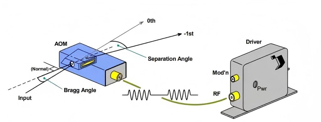
When you adjust the RF frequency, there might be an “invisible killer” causing damage in the dark, and that is the impedance mismatch of the drive circuit. Sometimes, when a spectrum analyzer is used to detect RF signals, the waveform looks quite clean, but the optical signal output by the AOM shows distortion. This is caused by impedance mismatch. If the impedance of the RF drive circuit and the AOM does not match (for example, if it is labeled as 50Ω but the actual deviation is too large), the signal will be reflected at the interface, resulting in energy loss and ultimately affecting the bandwidth.
How to detect?
- Measure the parameters of S11 with a vector network analyzer (VNA) to see if the reflection is severe.
- If the standing wave ratio (VSWR) is greater than 1.5, it indicates a problem with the matching.
Solution:
- Use broadband impedance matching circuits (such as Balun transformers).
- Avoid having the RF frequency approach the resonant point of the AOM; otherwise, standing waves will be generated, further deteriorating the signal quality.
Key Question 3: Why does the bandwidth get worse and worse after working for a long time?
The performance of AOM was very good when it first started working, but after running for a period of time, the modulation bandwidth decreased significantly. Even after increasing the RF drive power, the problem becomes more serious. This is because when high-frequency drive is used for a long time, the audio-visual medium is like an engine running at high speed for a long time, constantly heating up, causing changes in the speed of sound, and thus affecting the bandwidth.
Take TeO₂ (tellurium dioxide) as an example. For every 10°C increase in temperature, the speed of sound changes by approximately 0.5%, and the bandwidth may shift by more than 5%.
Solution:
Install TEC temperature control to maintain the stability of AOM temperature.
Choose materials with better thermal stability. For instance, lead molybdate (PM) is more stable than TeO₂ in some cases.
Optimize the heat dissipation design, such as forced air cooling or water cooling.
AOM Selection Quick Comparison Table
Compare the key parameters of different wavelengths (532nm/1064nm, etc.), RF frequencies, and applicable scenarios (lidar/quantum experiments, etc.):
| Wavelength | Recommended RF frequency | Maximum bandwidth | Applicable scenarios | Thermal management recommendations |
| 532nm | 80-120MHz | 50MHz | Bio-imaging | Air-cooled |
| 1064nm | 40-200MHz | 100MHz | Industrial cutting | TEC temperature control |
Practical advice: How to Optimize RF Frequency based on Demand?
Scene 1: High-speed communication (Priority bandwidth)
If your demand is high-speed communication, it’s like a car race that pursues ultimate speed. You should choose high-frequency RF (such as 200MHz), pair it with a small spot design, and at the same time select a medium with low thermal expansion (such as quartz) to maximize the bandwidth and make the signal transmission one step ahead.
Scene 2: High-power laser (Priority efficiency)
If the efficiency of high-power lasers is given more importance, it is like pursuing heavy machinery with high horsepower. Low-frequency RF (such as 50MHz) is suitable, combined with a large spot, and forced air cooling for heat dissipation to ensure the stable and efficient operation of the equipment.
Here is another list to avoid pitfalls to keep in mind: The RF frequency must never approach the AOM resonance point; otherwise, it would be like driving on a resonant bridge, which could trigger standing waves. The spot size should not exceed the wavelength of the sound wave either; otherwise, the diffraction efficiency will drop sharply, making your efforts in vain.
Conclusion
There is no “optimal” RF frequency; there is only the solution that best matches your needs. Bandwidth optimization is like a precise balancing operation. The key lies in doing a good job in collaborative design based on application scenarios. Only by taking into account factors such as RF frequency, audio-visual medium, spot size, circuit matching, and temperature control comprehensively can AOM fully demonstrate its true capabilities and no longer worry about insufficient modulation bandwidth.
Recommended Reading: Acousto-Optic Modulator (AOM) Selection Guide

